
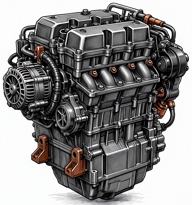
Problem Overview & Engine Systems
Cooling fan motor failure constitutes a significant malfunction within the engine’s thermal management system, leading directly to inadequate heat dissipation from the engine coolant. This critical component is an integral part of the Cooling System and the overall Electrical System, with its operation often managed by the Engine Management System (EMS) or a dedicated fan control module. Its primary function is to draw ambient air through the radiator and, if applicable, the A/C condenser, especially when the vehicle is stationary or moving at low speeds, or when the air conditioning system is active. A failure in the fan motor results in a compromised ability to maintain optimal engine operating temperatures. Directly affected internal components within the wider engine ecosystem include the radiator, engine coolant, thermostat, various temperature sensors (e.g., Engine Coolant Temperature – ECT sensor), and potentially the engine block and cylinder head if severe overheating occurs. The failure mechanism typically involves the motor’s electrical windings, bearings, or carbon brushes, leading to a complete cessation of function or intermittent operation.
Common Symptoms
- Primary Signs:
- Engine Coolant Temperature (ECT) Warning Lamp illuminating on the dashboard, often accompanied by the Check Engine Light (CEL) if Diagnostic Trouble Codes (DTCs) related to overheating or fan circuit malfunction are registered.
- The engine temperature gauge climbing rapidly into the hot zone, particularly during idle, low-speed driving, or in stop-and-go traffic.
- Steam or coolant boiling over from under the hood, often from the coolant reservoir cap or radiator cap.
- A distinct burning smell, possibly from overheated coolant or electrical components if the motor has shorted.
- Absence of the characteristic whirring noise of the cooling fan when the engine is hot and stationary. If the bearings are failing, a grinding or squealing noise might precede complete failure.
- Engine Behavior Changes:
- Noticeable engine overheating, leading to reduced engine performance as the Engine Management System (EMS) may initiate a “limp mode” to prevent catastrophic damage.
- Potential engine misfires or rough running due to excessive thermal stress on components like spark plugs, ignition coils, or fuel injectors.
- Premature detonation (pre-ignition or knocking) caused by high combustion chamber temperatures.
- If prolonged, severe overheating can lead to internal engine damage such as head gasket failure, warped cylinder heads, cracked engine blocks, or piston/cylinder wall scoring, manifesting as significant coolant loss, white exhaust smoke, or oil contamination.
Root Causes & Failure Mechanisms
- Electrical Component Degradation: The most frequent cause involves the internal electrical components of the fan motor. This includes degradation of the motor’s carbon brushes (in brushed DC motors) leading to intermittent contact or complete cessation, thermal breakdown of winding insulation causing short circuits or open circuits within the motor coils, or failure of the motor commutator segments due to wear or arcing.
- Bearing Failure: The motor’s internal bearings can degrade over time due to insufficient lubrication, ingress of moisture or dirt, or simply mechanical fatigue. This leads to increased friction, noise, excessive heat generation, and eventually bearing seizure, preventing the motor’s rotor from spinning.
- Fan Control Module (FCM) or Relay Malfunction: In many modern vehicles, a dedicated electronic fan control module or a conventional relay controls the fan motor operation and speed. These components can fail due to internal circuit board defects, power spikes, corrosion in the connectors, or worn relay contacts (sticking open or closed). This prevents the proper electrical signal or power supply from reaching the fan motor, even if the motor itself is healthy.
- Wiring Harness Damage: Physical damage, chafing, corrosion, or an open circuit within the wiring harness connecting the fan motor to its power source or control module can interrupt electrical flow, rendering the fan inoperative. Connectors can also become corroded or loose, creating high resistance points.
- Overload and Thermal Stress: Continuous operation in challenging conditions (e.g., hot climates, heavy towing, frequent stop-and-go traffic) without adequate cooling system maintenance can impose excessive thermal loads on the fan motor, accelerating insulation breakdown and internal component wear. Blocked radiator fins or a failing thermostat can exacerbate this by forcing the fan to work harder for longer.
How to Diagnose and Troubleshoot
Diagnosis of a cooling fan motor failure requires a methodical approach, combining visual inspection with electrical circuit testing:
- Initial Visual Inspection:
- Inspect the fan blades for any physical damage (cracks, missing pieces) or obstructions (debris, plastic bags) that might prevent free rotation.
- Check the fan shroud for integrity and proper mounting.
- Examine the wiring harness leading to the fan motor for signs of chafing, cuts, corrosion, or loose connections.
- Verify coolant levels and inspect for leaks around the radiator and hoses.
- Functional Test (OBD2 Scanner/Scan Tool):
- Connect an OBD2 scanner with bidirectional control capabilities to the vehicle’s diagnostic port.
- Navigate to the “Actuators” or “Output Controls” menu and command the cooling fan(s) ON and OFF at various speeds if applicable. Observe if the fan responds.
- While monitoring the fan’s operation, also observe the Engine Coolant Temperature (ECT) sensor reading on the scanner to ensure it’s accurate and triggers the fan at the correct threshold. If the fan doesn’t activate, proceed to electrical checks.
- Electrical Circuit Testing (Multimeter):
- Power Supply Check: Disconnect the fan motor electrical connector. Using a digital multimeter, measure voltage at the power terminal(s) of the connector when the fan is commanded ON (via scan tool) or when the engine is sufficiently hot to activate the fan. A reading close to battery voltage (e.g., 12V-14V) indicates proper power supply from the relay/module.
- Ground Circuit Check: Verify continuity between the ground terminal of the fan motor connector and a known good chassis ground. A reading of less than 0.5 ohms is desirable.
- Fan Motor Resistance Test: With the fan motor disconnected from the harness, measure the resistance across the motor’s power and ground terminals. A reading of high resistance (indicating an open circuit) or a very low resistance (indicating a short circuit) often points to an internal motor failure. A functional motor typically has a low resistance value (e.g., 0.5 to 3 ohms), but specific values vary by application.
- Fan Relay Test: Locate the fan relay (often in the under-hood fuse box). Test its operation by swapping it with a known good relay, or by manually applying 12V to the coil terminals and checking continuity across the switch terminals with a multimeter. Inspect the relay socket for corrosion.
- Fan Control Module (FCM) Test: If equipped, verify power and ground to the FCM and confirm it is receiving the correct activation signal from the EMS. Output signals from the FCM to the fan motor can be more complex (e.g., Pulse Width Modulation – PWM) and may require an oscilloscope for thorough analysis, though a simple voltage check at the motor connector during commanded operation can often suffice.
- DTC Retrieval: Use the OBD2 scanner to check for any stored DTCs, such as P0480 (Fan 1 Control Circuit), P0481 (Fan 2 Control Circuit), P0482 (Fan 3 Control Circuit), or general overheating codes (e.g., P0217 – Engine Over Temperature Condition). These codes provide valuable direction for diagnosis.
Recommended Repairs and Solutions
The primary repair for a cooling fan motor failure is typically the replacement of the faulty component. The scale of repair is generally manageable and does not usually escalate to a complete engine overhaul unless significant secondary damage has occurred due to prolonged, severe overheating.
- Cooling Fan Motor Assembly Replacement: In most cases, the entire cooling fan motor, along with its associated fan blades and often the shroud, is replaced as a complete assembly. This is the most common and effective solution for internal motor failures (brushes, bearings, windings). Ensure the replacement part is an OEM equivalent or a high-quality aftermarket unit to guarantee proper fit, performance, and longevity.
- Fan Control Module or Relay Replacement: If diagnostic steps identify the fan control module or relay as the root cause, these components will need to be replaced. These are typically plug-and-play components, though some control modules may require programming or configuration using a specialized scan tool after installation.
- Wiring Harness Repair: If the fault is localized to the wiring harness (chafed wires, corroded connectors), the damaged section should be professionally repaired by soldering and heat-shrinking new wire sections, or by replacing the specific connector. Avoid using crimp connectors in critical engine compartment areas due to potential for corrosion.
- Engine Coolant Temperature (ECT) Sensor Replacement: If the ECT sensor is found to be providing inaccurate readings, leading to incorrect fan activation, it should be replaced. This is a relatively inexpensive and straightforward repair.
Driving Safety Risk Factors: Driving with an inoperative cooling fan poses a HIGH safety risk to the engine. Without proper cooling, the engine can quickly overheat, especially in heavy traffic, at idle, or in hot weather. Prolonged overheating can lead to severe and irreversible engine damage, including: head gasket failure, warped or cracked cylinder heads, piston and cylinder wall damage, and potentially complete engine seizure. If the cooling fan is confirmed to be inoperative and the engine temperature gauge indicates overheating, the vehicle should not be driven. Pull over safely, allow the engine to cool, and arrange for towing to a repair facility to prevent catastrophic engine failure.
Maintenance Recommendations
Proactive maintenance of the cooling system and its components is crucial to prevent cooling fan motor failure and ensure optimal engine thermal management:
- Regular Cooling System Inspection:
- Periodically (e.g., at every oil change or annually) visually inspect the cooling fan for any signs of physical damage to the blades or shroud.
- Ensure the fan spins freely by hand when the engine is off and cool. Listen for any unusual noises (grinding, squealing) during fan operation.
- Inspect the fan motor’s electrical connector and wiring harness for signs of corrosion, damage, or loose connections.
- Verify that the radiator and A/C condenser fins are free from debris (leaves, insects, dirt) which can impede airflow and force the fan to work harder.
- Coolant System Flushing and Replenishment:
- Adhere strictly to the manufacturer’s recommended service intervals for cooling system flush and fill. This typically ranges from every 30,000 to 100,000 miles or every 2 to 5 years, depending on the coolant type (e.g., OAT, HOAT, POAT, Conventional Green).
- Always use the specified coolant type and concentration recommended by the vehicle manufacturer. Incorrect coolant can lead to corrosion, reduced heat transfer efficiency, and premature component failure within the cooling system, increasing the load on the fan.
- Component Lifespan and Proactive Replacement:
- While cooling fan motors are not typically a scheduled replacement item, consider proactive replacement on high-mileage vehicles (e.g., over 150,000 miles) if the fan shows signs of intermittent operation, excessive noise, or reduced performance, especially if residing in a hot climate or frequently towing.
- Consider replacing the Engine Coolant Temperature (ECT) sensor during major cooling system overhauls (e.g., water pump replacement, radiator replacement) as a preventative measure, as an inaccurate sensor can prevent proper fan activation.
- Operational Habits:
- Regularly monitor the engine temperature gauge while driving, especially in heavy traffic, uphill climbs, or hot weather. Any consistent deviation from the normal operating temperature should be investigated promptly.
- Avoid excessive engine idling in high ambient temperatures, particularly if the fan’s operation is suspect.
- If the engine temperature gauge begins to climb, turn off the air conditioning (to reduce condenser heat load) and, if safe to do so, turn on the heater to full blast (to draw heat away from the engine).
