
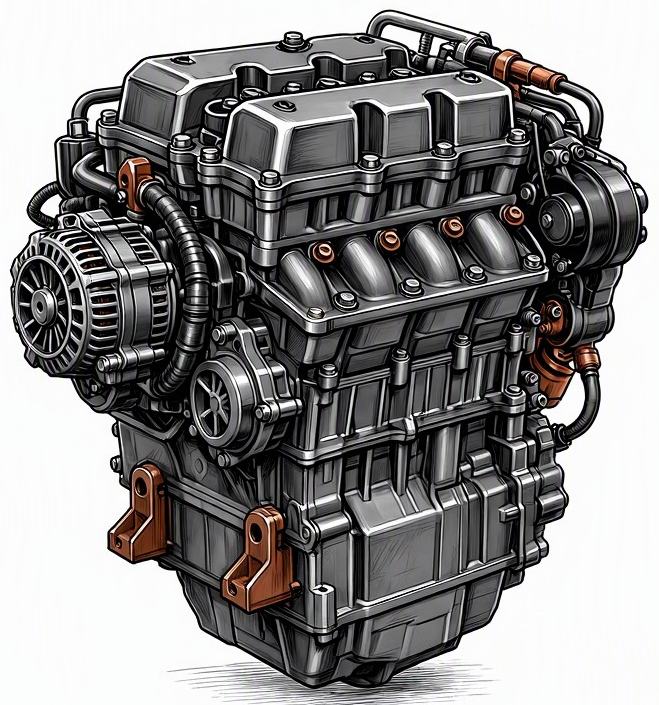
Problem Overview & Engine Systems
Knock sensor failure constitutes a critical malfunction within the internal combustion engine’s sophisticated Engine Management System (EMS), specifically impacting the Powertrain Control Module’s (PCM) ability to optimize ignition timing. The knock sensor, typically a piezoelectric accelerometer, is meticulously calibrated to detect the high-frequency vibrations characteristic of engine detonation or pre-ignition, commonly referred to as “knock.” These deleterious combustion events occur when the air-fuel mixture ignites prematurely or combusts uncontrollably after the spark plug fires, generating destructive pressure waves within the combustion chamber. The sensor, usually mounted directly onto the engine block, cylinder head, or sometimes the intake manifold, converts these mechanical vibrations into an electrical signal that is then transmitted to the PCM. Upon receiving this signal, the PCM initiates a corrective strategy, most notably by retarding ignition timing and, in some cases, adjusting fuel delivery, to mitigate the knocking event and prevent catastrophic engine damage. When a knock sensor fails, the PCM is deprived of this vital feedback. This can lead to two primary scenarios: either the PCM defaults to an excessively conservative, retarded timing strategy (a “limp mode”) to avoid potential knock, resulting in significant performance degradation, or, more dangerously, it fails to detect and react to actual knocking, leaving the engine vulnerable to severe internal damage. The internal components directly affected by the consequences of undetected knock include the pistons (particularly ring lands and crowns), connecting rods, crankshaft bearings, cylinder walls, valves, and the cylinder head itself, as sustained detonation can cause erosion, pitting, and even structural compromise to these metallic components.
Common Symptoms
- Primary Signs:
- Illumination of the Check Engine Light (CEL) on the instrument cluster.
- Storage of Diagnostic Trouble Codes (DTCs) in the PCM, commonly in the P032X series (e.g., P0325 – Knock Sensor 1 Circuit Malfunction, P0326 – Knock Sensor 1 Range/Performance, P0327 – Knock Sensor 1 Low Input, P0328 – Knock Sensor 1 High Input, P0329 – Knock Sensor 1 Intermittent).
- A distinct audible “pinging,” “rattling,” or “marbles in a can” sound, particularly noticeable during acceleration or under load, if the PCM fails to adequately retard timing and actual detonation occurs.
- Reduced fuel economy due to inefficient combustion or the PCM’s default retarded timing strategy.
- Engine Behavior Changes:
- Pronounced loss of engine power and reduced acceleration, resulting from the PCM’s compensatory strategy of excessively retarding ignition timing to prevent potential knock.
- Noticeable hesitation or stumbling during throttle application.
- Reduced throttle response, making the vehicle feel sluggish or unresponsive.
- Rough running or a general lack of smoothness in engine operation, especially under varying loads.
- In severe cases where true knock goes unmitigated, there is an elevated risk of internal engine damage over time.
Root Causes & Failure Mechanisms
- Electrical Circuit Degradation: The most prevalent cause involves the electrical integrity of the sensor or its associated wiring. This includes an open circuit (e.g., a broken wire within the harness, corroded pin in the connector, or an internal fracture of the piezoelectric element), a short circuit (where the signal wire contacts ground or another wire, leading to an incorrect signal), or excessive resistance buildup due to corrosion at connection points or internal degradation of the sensor’s conductive pathways.
- Piezoelectric Element Failure: The core of the knock sensor is its piezoelectric material (e.g., lead zirconate titanate ceramic). Over prolonged operational cycles, this material can degrade due to relentless mechanical vibration, thermal cycling (exposure to extreme engine temperatures), or moisture intrusion. This degradation diminishes the element’s ability to accurately convert mechanical vibrations into a discernible electrical signal, leading to reduced sensitivity or complete signal loss.
- Environmental and Mechanical Damage: Physical impact during unrelated engine work, exposure to corrosive fluids (e.g., coolant leaks, road salt), or abrasion from contact with other engine components can compromise the sensor’s housing, wiring insulation, or connector. Rodent damage to the wiring harness is also a common occurrence.
- Mounting Integrity Compromise: The knock sensor’s effectiveness is highly dependent on its proper mechanical coupling to the engine block. Improper torque during installation (either undertorqued, leading to poor signal transmission, or overtorqued, which can damage the sensor housing) or degradation of the mounting surface can significantly impair the sensor’s ability to accurately detect vibrations.
- Internal Contamination: While less common, manufacturing defects or internal seal failures can allow moisture or oil to enter the sensor housing, contaminating the piezoelectric element or electrical connections, leading to erratic operation or failure.
How to Diagnose and Troubleshoot
Diagnosis of a knock sensor failure requires a methodical approach, leveraging both specialized diagnostic equipment and fundamental electrical testing principles:
- Retrieve Diagnostic Trouble Codes (DTCs): Connect an OBD2 scanner to the vehicle’s diagnostic port. Extract any stored DTCs, specifically looking for P0325 through P0329, which directly point to knock sensor circuit malfunctions. Note any accompanying misfire codes (P030X) as a secondary symptom potentially induced by timing issues.
- Analyze Live Data Stream: Utilize the OBD2 scanner to monitor live engine data. Observe parameters such as ignition timing advance/retard. If the knock sensor is faulty, the PCM may consistently show excessive timing retard or a complete absence of timing adjustments in response to engine load, indicating a “limp home” mode. Some advanced scanners may display raw knock sensor voltage readings; look for a flat-line signal (indicating no output) or erratic, uncharacteristic spikes.
- Visual Inspection of Wiring and Connector: Physically inspect the knock sensor’s wiring harness for visible damage, including fraying, cuts, chafing, or signs of rodent activity. Examine the electrical connector for corrosion, bent pins, or proper seating. Ensure the harness is securely routed away from hot or moving engine components.
- Multimeter Electrical Tests:
- Resistance Test: Disconnect the knock sensor. Using a digital multimeter (DMM) set to ohms, measure the internal resistance across the sensor’s terminals. Refer to the vehicle’s specific service manual for the expected resistance range (typically in the hundreds of kOhms to several MOhms). An open circuit (infinity/OL) or a resistance value significantly outside the specified range indicates an internal sensor failure.
- Output Voltage Test (Dynamic): While the sensor is connected to the harness and the engine is running (or key on, engine off), gently tap the engine block near the sensor with a rubber mallet. Use a DMM set to AC voltage to monitor the sensor’s output. A functioning piezoelectric sensor should produce a momentary AC voltage spike (typically in the millivolt range) in response to the impact. A completely flat line indicates a non-responsive sensor.
- Circuit Continuity to PCM: With the battery disconnected and both the knock sensor and PCM connectors detached, use the DMM to test continuity of each wire from the sensor connector back to the corresponding pin on the PCM connector. This verifies the integrity of the wiring harness itself. Check for shorts to ground or power.
- Oscilloscope Analysis (Advanced): For definitive diagnosis, connect an oscilloscope to the knock sensor’s signal wire. Monitor the waveform while the engine is running under various loads. A healthy knock sensor will produce a characteristic AC voltage signal that increases in amplitude and frequency with actual engine knock. A failed sensor will exhibit a flat line, excessive noise without a discernible pattern, or an erratic, non-responsive signal.
- PCM Input Verification: If the sensor and wiring test correctly, the issue could reside within the PCM’s input circuit. This requires specialized equipment and expertise to test voltage reference signals and signal processing capabilities at the PCM connector.
Recommended Repairs and Solutions
The primary and most frequent repair for a diagnosed knock sensor failure is the direct replacement of the faulty component. Given the critical role of the knock sensor in preventing engine damage, it is crucial to use an OEM-quality replacement part. The repair scale is typically localized component replacement:
- Knock Sensor Replacement:
- Accessing the knock sensor can range from straightforward to highly involved, often requiring the removal of intake manifolds, throttle bodies, or other peripheral components, depending on the engine design and sensor location.
- During installation, strict adherence to the manufacturer’s specified torque value is paramount. Overtorquing can damage the new sensor, while undertorquing can compromise its ability to accurately transmit vibrations, leading to persistent issues or inaccurate readings.
- Always replace any damaged wiring harnesses or corroded electrical connectors during the sensor replacement process to ensure signal integrity.
- Wiring Harness Repair/Replacement: If the diagnosis points to a damaged wiring harness rather than the sensor itself, the damaged section should be meticulously repaired using proper soldering techniques, heat-shrink tubing, and appropriate gauge wire, or the entire harness section replaced if damage is extensive.
- PCM Software Update/Replacement: In rare instances, a PCM reflash or software update might be available from the manufacturer to address known issues related to knock sensor algorithms. If internal PCM circuitry related to the knock sensor input is confirmed faulty, PCM replacement would be necessary, though this is a less common resolution for a primary knock sensor fault.
Driving Safety Risk Factors: Operating a vehicle with a failed knock sensor carries a moderate to high safety risk to the engine’s longevity. If the PCM defaults to a safe, highly retarded ignition timing map, engine performance will be severely compromised, making acceleration and merging maneuvers potentially hazardous due to lack of power. More critically, if the knock sensor fails to detect actual engine detonation and the PCM continues to operate with aggressive timing, sustained internal engine damage (e.g., piston crown erosion, ring land collapse, bent connecting rods, or damaged bearings) can occur rapidly, leading to costly major engine repairs or even complete engine failure. Therefore, prompt diagnosis and repair are strongly recommended.
Maintenance Recommendations
While knock sensors do not typically have a specified service interval and are generally considered “lifetime” components, several maintenance practices can contribute to their longevity and the overall health of the engine management system:
- Routine Visual Inspections: During other routine engine maintenance (e.g., spark plug replacement, intake manifold cleaning, coolant flushes), visually inspect the knock sensor and its wiring harness. Look for signs of physical damage, corrosion, chafing, or degradation of the wiring insulation. Ensure all connectors are securely seated.
- Use of Recommended Fuel Octane: Always adhere to the manufacturer’s specified fuel octane rating. Using lower octane fuel than recommended significantly increases the likelihood of engine knock, forcing the knock sensor and PCM to work harder and constantly adjust timing, which can mask minor sensor degradation or put undue stress on the system.
- Address Engine Carbon Buildup: Excessive carbon deposits on piston crowns and valves can create hot spots within the combustion chamber, promoting pre-ignition and knock. Regular fuel system cleaning and adherence to oil change intervals using manufacturer-specified oil can help mitigate carbon accumulation.
- Maintain Engine Cooling System: An efficiently operating cooling system prevents engine overheating, which can exacerbate knocking conditions and place additional thermal stress on engine components, including the knock sensor. Ensure proper coolant levels and regular coolant system maintenance.
- Avoid Aftermarket Modifications: Be judicious with aftermarket engine modifications, particularly those affecting ignition timing or fuel delivery, as these can alter the engine’s combustion characteristics and potentially induce knock beyond the knock sensor’s intended operational range. If modifications are made, ensure proper tuning by a qualified professional.
- Promptly Address Check Engine Light: Do not ignore an illuminated Check Engine Light. While not all CELs indicate a knock sensor issue, prompt professional diagnosis can identify and resolve potential problems before they lead to more significant engine damage.
