
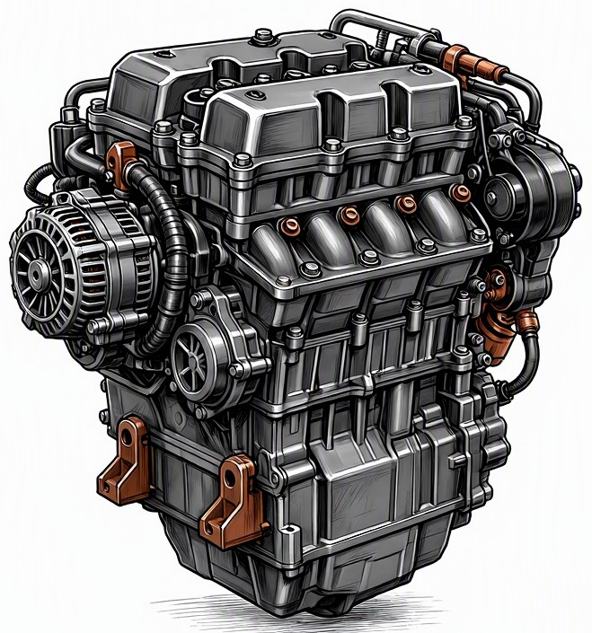
Problem Overview & Engine Systems
Oxygen sensor lazy response refers to a condition where the oxygen (O2) sensor, primarily the upstream or pre-catalytic converter sensor (often designated as Sensor 1), fails to rapidly switch its voltage output between rich (high voltage, typically 0.6-0.9V for Zirconia sensors) and lean (low voltage, typically 0.1-0.3V) signals. This slow switching behavior prevents the Engine Control Module (ECM) or Powertrain Control Module (PCM) from accurately and promptly adjusting the air-fuel ratio to stoichiometry (lambda = 1), which is critical for optimal combustion efficiency and catalytic converter operation. A healthy O2 sensor should oscillate rapidly, indicating precise feedback to the ECM’s closed-loop fuel control system.
This malfunction primarily impacts the Engine Management System (EMS), specifically the Fuel Control System and Emissions Control System. While the sensor itself is a component of the exhaust system, its function is integral to the ECM’s ability to manage fuel delivery. Internally, the O2 sensor’s zirconia element (or titania for some types) becomes less reactive. The direct consequence is that the ECM operates with stale data, leading to delayed or inaccurate adjustments to the Fuel Injectors pulse width. This can result in either a consistently rich or lean mixture, leading to incomplete combustion and overloading the Catalytic Converter, thereby reducing its efficiency and lifespan. The internal components directly affected are the sensor’s sensing element and its associated heater circuit (if equipped).
Common Symptoms
- Primary Signs:
- Check Engine Light (CEL) illumination with specific Diagnostic Trouble Codes (DTCs) such as P0133 (O2 Sensor Circuit Slow Response – Bank 1, Sensor 1), P0134 (O2 Sensor Circuit No Activity Detected – Bank 1, Sensor 1), P0153 (O2 Sensor Circuit Slow Response – Bank 2, Sensor 1), or P0154 (O2 Sensor Circuit No Activity Detected – Bank 2, Sensor 1).
- Potential increase in tailpipe emissions, sometimes manifesting as black smoke from the exhaust during acceleration due to a rich mixture, or a noticeable smell of unburnt fuel.
- Engine Behavior Changes:
- Reduced Fuel Economy: The ECM’s inability to maintain a stoichiometric air-fuel ratio often results in a richer mixture, consuming more fuel.
- Rough Idle or Fluctuating Idle Speed: Inconsistent fuel delivery can cause the engine to run unevenly, particularly at idle.
- Hesitation or Poor Acceleration: The engine may feel sluggish or unresponsive to throttle input as the fuel trim adjustments lag behind changing engine loads.
- Increased Exhaust Emissions: Direct result of suboptimal combustion and reduced catalytic converter efficiency.
- Subtle Power Loss: While not always severe, a decrease in peak engine performance can be observed.
Root Causes & Failure Mechanisms
- Thermal Degradation and Contamination: Prolonged exposure to high exhaust temperatures, coupled with deposits from oil ash, unburnt fuel, or silicone/antifreeze contamination (e.g., from a head gasket leak), can coat the sensor’s ceramic sensing element. This creates a physical barrier, slowing the diffusion of oxygen ions to and from the active sensing surface, thus impeding its ability to respond quickly to changes in oxygen concentration.
- Aging and Material Fatigue: Over time, the internal reference electrode and the zirconia element itself can degrade or become less porous. The platinum electrodes, which catalyze the oxygen reactions, can also lose effectiveness. This inherent material aging increases the sensor’s internal resistance and reduces its chemical reactivity, leading to a slower response rate. The heater element within the sensor can also weaken, taking longer to bring the sensor to its optimal operating temperature (typically 300-600°C), further exacerbating slow response issues during cold engine operation.
- Wiring and Connector Degradation: Damage, corrosion, or poor electrical contact in the sensor’s wiring harness or connector can lead to increased electrical resistance. This impedes the rapid transmission of the sensor’s micro-voltage signal to the ECM, making the ECM “see” a slow response even if the sensor element itself is still reactive.
- Exhaust Leaks: Upstream exhaust leaks between the engine and the oxygen sensor can draw in ambient air, artificially leaning out the exhaust gas reaching the sensor. While this might not directly cause “lazy response,” it can confuse the ECM and lead to incorrect fuel trim corrections that indirectly stress the sensor or mimic a slow response as the ECM tries to react to erroneous data.
How to Diagnose and Troubleshoot
Diagnosis of a lazy oxygen sensor requires specific tools and a systematic approach to differentiate it from other fuel system or engine issues:
- OBD2 Scanner Data Analysis:
- Retrieve DTCs: Begin by checking for relevant trouble codes (P0133, P0134, P0153, P0154). Note any other codes that might indicate underlying issues.
- Monitor Live Data – O2 Sensor Voltage: With the engine at operating temperature and in closed-loop operation (typically indicated by “CL” status on the scanner), observe the upstream O2 sensor voltage readings. A healthy zirconia sensor should rapidly oscillate between approximately 0.1V (lean) and 0.9V (rich) multiple times per second (typically 8-12 switches per 10 seconds at 2500 RPM steady state). A lazy sensor will show slower, smoother, or wider transitions, spending more time in the mid-range voltage (e.g., 0.45V) or taking significantly longer to switch from rich to lean or vice-versa.
- Monitor Live Data – Fuel Trims (STFT & LTFT): Observe Short-Term Fuel Trims (STFT) and Long-Term Fuel Trims (LTFT). Persistently high positive or negative trims can indicate the ECM struggling to compensate for inaccurate O2 sensor feedback. If the sensor is lazy and indicating a false lean condition, the ECM will add fuel (positive trims); if it indicates a false rich condition, the ECM will remove fuel (negative trims).
- Oscilloscope Waveform Analysis: This is the most precise method. Backprobe the O2 sensor signal wire at the sensor or ECM connector (consult wiring diagrams). An oscilloscope will display the sensor’s voltage output as a waveform. A lazy sensor will exhibit a rounded, delayed, or attenuated waveform compared to the sharp, square-wave-like transitions of a healthy sensor. Measure the “transition time” (time taken to switch from rich to lean or lean to rich); this should be very quick, typically under 100 milliseconds.
- Propane Enrichment / Vacuum Leak Test:
- Propane Enrichment: With the engine idling, briefly introduce an unlit propane torch (or carburetor cleaner if safe and cautious) into the intake manifold near a vacuum port. This creates a momentarily rich condition. A healthy O2 sensor should respond almost instantly by switching to a high voltage (rich) and the STFT should drop significantly. A lazy sensor will show a delayed or weak response.
- Vacuum Leak: Briefly create a controlled vacuum leak (e.g., by carefully pulling a small vacuum hose) to introduce extra air, creating a momentary lean condition. A healthy O2 sensor should quickly drop to a low voltage (lean) and the STFT should increase significantly. A lazy sensor will exhibit a delayed or insufficient reaction.
- Heater Circuit Check: Using a multimeter, test the O2 sensor’s heater element resistance (when cold, according to specifications) and verify 12V power supply and ground to the heater circuit when the engine is running or key is on. A failing heater can significantly prolong the time the sensor takes to reach operating temperature, leading to slow response during warm-up or colder ambient conditions.
- Visual Inspection: Carefully inspect the O2 sensor body and tip for heavy carbon buildup, oil residue, coolant staining (green/orange), or physical damage. Also, check the wiring harness for fraying, corrosion, or rodent damage.
Recommended Repairs and Solutions
The primary solution for an oxygen sensor lazy response is the replacement of the faulty sensor. The following steps and considerations apply:
- Oxygen Sensor Replacement: Replace the affected upstream oxygen sensor (Bank 1, Sensor 1 or Bank 2, Sensor 1, as identified by DTCs or diagnostic testing). It is crucial to use a direct OEM equivalent or a high-quality, reputable aftermarket sensor that meets or exceeds OEM specifications. Universal sensors requiring splicing are generally not recommended due to potential signal integrity issues.
- Address Underlying Contamination Issues: If diagnostic inspection revealed sensor contamination (e.g., heavy oil ash, coolant), the root cause of this contamination must be resolved to prevent premature failure of the new sensor. This might involve engine repairs such as addressing excessive oil consumption, fixing a head gasket leak, or repairing fuel injector issues.
- Wiring Harness Repair: If the issue was identified as degraded wiring or a faulty connector, the affected section of the wiring harness should be repaired using appropriate automotive-grade connectors and soldering techniques, or replaced if extensive.
- Clear DTCs and ECM Relearn: After replacing the sensor and addressing any underlying issues, clear all stored DTCs from the ECM. It is often beneficial to perform a drive cycle or specific relearn procedure (if applicable for the vehicle) to allow the ECM to adapt to the new sensor and optimize fuel trims.
Repair Scale: This issue typically involves a straightforward component replacement and is considered a relatively minor repair, not requiring major engine disassembly or overhaul.
Driving Safety Risk Factors: While not an immediate safety hazard that would cause sudden vehicle immobilization, a lazy O2 sensor compromises vehicle performance, increases emissions, and can lead to long-term damage. Prolonged rich running can significantly shorten the lifespan of the expensive catalytic converter, leading to additional costly repairs. It also impacts fuel economy and can cause the vehicle to fail emission tests.
Maintenance Recommendations
Preventing oxygen sensor lazy response largely revolves around maintaining overall engine health and following manufacturer service guidelines:
- Regular Engine Tune-ups: Ensure the engine receives regular maintenance, including timely replacement of spark plugs, inspection of ignition coils, and servicing of fuel injectors. A properly tuned engine minimizes incomplete combustion, which can lead to carbon buildup and stress on the O2 sensor.
- Adhere to Oil Change Intervals: Follow the manufacturer’s recommended oil change intervals and use the specified oil type and viscosity. This helps prevent excessive oil consumption and associated oil ash deposits that can contaminate the O2 sensor.
- Prompt Repair of Fluid Leaks: Immediately address any oil, coolant, or exhaust leaks. Coolant (antifreeze) and excessive oil entering the exhaust system are highly detrimental to oxygen sensors, causing rapid contamination and failure. Exhaust leaks upstream of the O2 sensor can also introduce unmetered air, skewing readings.
- Use Quality Fuel: Utilize high-quality, reputable fuels and avoid excessive use of aftermarket fuel additives, which can sometimes leave harmful deposits on sensors.
- Consider Proactive Replacement: While not always mandated, some automotive experts recommend proactive replacement of upstream oxygen sensors every 60,000 to 100,000 miles, especially in vehicles known for sensor degradation, as their efficiency naturally declines over time even without catastrophic failure. This can help maintain optimal fuel economy and emissions performance.
- Monitor Dash Warnings: Address any illuminated Check Engine Light promptly. Early diagnosis and repair of related engine issues can prevent secondary damage to the oxygen sensor.
