
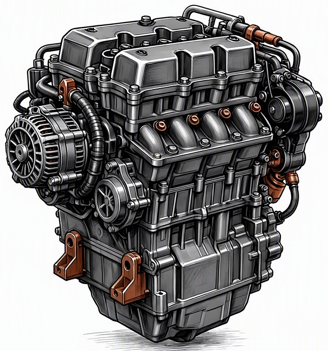
Problem Overview & Engine Systems
The condition “Mechanical lifter out of adjustment,” commonly referred to as incorrect valve lash, describes a critical deviation from the manufacturer’s specified clearance within the engine’s valvetrain. Mechanical lifters, also known as solid tappets, transmit the camshaft’s lobe profile directly to the valve stem (either directly in direct-acting overhead cam designs or via a pushrod and rocker arm in pushrod designs). Proper valve lash is the precise clearance engineered to accommodate thermal expansion of valvetrain components as the engine reaches operating temperature, ensuring the valves fully close and open at the correct times.
This malfunction primarily affects the Valvetrain system, which is an integral part of the Cylinder Head assembly. The valvetrain is responsible for precisely controlling the intake and exhaust valves, allowing air-fuel mixture into the cylinders and expelling exhaust gases. When valve lash is out of adjustment, it directly impacts the precise timing and lift of these valves. Internally, the primary components directly affected include the camshaft lobes, the mechanical lifter (tappet) itself, the pushrod (if present), the rocker arm (if present), the valve stem tip, and ultimately the valve seat and valve face. Improper lash can lead to excessive wear on these components and compromise valve sealing, impacting combustion efficiency and potentially leading to premature valve component failure.
Common Symptoms
- Primary Signs:
- Audible Noise: A distinct, rhythmic “ticking” or “clattering” noise emanating from the cylinder head area. This sound is often described as resembling a sewing machine. If lash is too great, the noise is generally louder and more pronounced, particularly when the engine is cold and typically lessens slightly as the engine warms and components expand. If lash is too small, there may be little or no audible noise, but valve train wear or burning may occur.
- Check Engine Light (CEL): May illuminate if severe misfires occur due to improper valve sealing, triggering diagnostic trouble codes (DTCs) such as P030x (Cylinder Misfire Detected).
- No Direct Low Oil Pressure Warning: This issue does not directly cause low oil pressure, though severe, prolonged neglect leading to component damage could indirectly affect oil passages.
- Engine Behavior Changes:
- Engine Misfires: Particularly noticeable under load or at specific RPM ranges, resulting from either a valve not fully closing (insufficient lash) or not fully opening (excessive lash), leading to incomplete combustion.
- Reduced Engine Power and Torque: Compromised volumetric efficiency due to incorrect valve timing or incomplete valve lift/closure directly reduces engine output.
- Rough Idle / Fluctuating Idle Speed: Inconsistent cylinder combustion caused by varied valve operation across cylinders leads to an unstable idle.
- Hesitation or Poor Throttle Response: The engine may feel sluggish or unresponsive to throttle inputs due to compromised breathing.
- Increased Exhaust Emissions: Incomplete combustion due to improper valve operation results in higher levels of unburnt hydrocarbons (HC) and carbon monoxide (CO) in the exhaust.
- Potential Hard Starting: In extreme cases of insufficient lash, a valve may be held slightly open even during the compression stroke, leading to a loss of compression and difficulty starting the engine.
Root Causes & Failure Mechanisms
- Manufacturing Tolerance Variation or Initial Adjustment Error: Incorrect initial setting of valve lash during engine assembly or a prior valvetrain service is a common root cause. This could be due to human error, improper tooling, or using incorrect specifications.
- Gradual Wear and Tear: Over extended periods of operation, the surfaces of valvetrain components such as the camshaft lobes, lifter faces, rocker arms, and valve stem tips can experience abrasive and adhesive wear. This wear typically increases the existing clearance (excessive lash) over time.
- Thermal Cycling Effects: Repeated cycles of heating and cooling can induce minor material changes or settling in valvetrain components. While components are designed to tolerate this, cumulative effects can subtly alter lash, especially if the initial adjustment was at the edge of the specification.
- Component Settling or Break-in: Newly installed valvetrain components (e.g., during an engine rebuild or cylinder head replacement) may experience a “settling in” period. This can cause slight dimensional changes that drift the lash out of specification after initial operation.
- Lack of Regular Maintenance: Engines equipped with mechanical lifters inherently require periodic valve lash adjustment as a scheduled maintenance item. Neglecting these service intervals allows wear to accumulate unchecked, leading to significant deviations from the specified lash.
- Incorrect Component Specification or Quality: Use of aftermarket valvetrain components that do not meet OEM specifications for hardness, material composition, or dimensions can accelerate wear or result in lash that is impossible to correctly set or maintain.
How to Diagnose and Troubleshoot
Diagnosing mechanical lifter out of adjustment requires a systematic, hands-on approach. Precision and adherence to manufacturer specifications are paramount.
- Initial Auditory Assessment: Begin by listening to the engine with a mechanic’s stethoscope. Carefully trace the ticking noise to pinpoint its exact origin within the cylinder head area. Note if the noise intensity changes with engine temperature or RPM.
- Consult Service Manual: Obtain the vehicle manufacturer’s service manual for the specific engine. This will provide critical specifications for valve lash (hot and cold), adjustment procedures, and cylinder identification.
- Valve Cover Removal: Allow the engine to cool sufficiently, then carefully remove the valve cover(s) to gain direct access to the valvetrain components.
- Crankshaft Positioning and Camshaft Lobe Positioning: Using a specialized crankshaft turning tool or a wrench on the crankshaft pulley bolt, slowly rotate the engine’s crankshaft manually. For accurate lash measurement, each valve must be positioned such that its respective camshaft lobe is on its “base circle” (the portion of the lobe where the valve is fully closed and the lifter is at its lowest point). This ensures there is no lift action affecting the measurement. Follow the service manual’s specific cylinder-by-cylinder procedure for bringing each set of valves to the base circle.
- Feeler Gauge Measurement: With the camshaft lobe on its base circle, use a precisely calibrated set of feeler gauges to measure the clearance.
- Direct Acting Lifters (Shim-under/over-bucket): Measure between the cam lobe and the top of the lifter bucket.
- Pushrod/Rocker Arm Systems: Measure between the rocker arm and the valve stem tip.
The feeler gauge of the specified thickness should slide in with a slight drag. Compare the measured lash to the manufacturer’s specified hot or cold clearance, as applicable. Note all measurements, identifying which are excessively loose or tight.
- Visual Inspection for Wear: While the valve cover is off, thoroughly inspect the camshaft lobes for pitting, scoring, or excessive wear. Examine the lifter faces (or bucket surfaces), rocker arm pads, and valve stem tips for any signs of wear, pitting, or damage that would indicate a need for component replacement in addition to adjustment.
- Compression Test / Leak-Down Test (If Misfires Present): If significant power loss or misfires are present, perform a compression test or a leak-down test on the affected cylinders. Low compression or high leakage on a specific cylinder can confirm a valve not fully closing (due to insufficient lash or physical damage).
- OBD-II Scan (If CEL is On): Use an OBD-II scanner to retrieve any stored DTCs. Misfire codes (P030x) can help narrow down the cylinders requiring closer inspection.
Recommended Repairs and Solutions
The primary repair for mechanical lifter out of adjustment is the precise adjustment of valve lash back to manufacturer specifications. The method of adjustment varies significantly depending on the engine design:
- Adjustable Rocker Arms (e.g., Screw-and-Locknut Type): This is the most straightforward method. With the valve on its base circle, a feeler gauge is inserted, the locknut is loosened, and the adjusting screw is turned until the correct drag is felt on the feeler gauge. The locknut is then tightened securely while carefully re-checking the lash.
- Shim-Under-Bucket or Shim-Over-Bucket Lifters: This method is more involved.
- The existing valve lash is measured.
- The camshaft is typically removed (or specific tools used to depress the valve spring) to access the lifter bucket.
- The lifter bucket is removed, and the existing shim thickness is measured (often with a micrometer).
- A calculation is performed based on the measured lash, the desired lash, and the existing shim thickness to determine the required thickness of the new shim.
- A new shim of the correct thickness is installed, the lifter bucket replaced, and the lash re-measured to confirm accuracy. This often requires a specialized shim kit with a range of thicknesses.
Component Replacement:
- If significant wear (pitting, spalling, deep scoring) is found on the camshaft lobes, lifter faces, or rocker arms, these components should be replaced. Merely adjusting the lash on worn components will only temporarily alleviate the symptoms, and accelerated wear will continue.
- If inspection reveals damage to valve stems, valve seats, or valve guides (e.g., due to prolonged insufficient lash causing valve burning), then cylinder head removal and professional machine shop work (e.g., valve replacement, valve seat grinding, guide replacement) will be necessary.
Repair Scale: For simple lash adjustment, it is typically a targeted service requiring removal of valve covers. If components like camshafts or lifters need replacement, the repair scale increases significantly, potentially involving timing component removal (belts/chains) and partial engine disassembly. A full engine overhaul is generally not required unless severe secondary damage (e.g., broken valve, piston impact) has occurred due to extreme neglect.
Driving Safety Risk Factors: Moderate. While not immediately catastrophic, untreated severe lash issues can lead to progressive valvetrain damage, including broken valve springs, bent pushrods, or cam lobe failure. In extreme cases of insufficient lash, valves can burn or even break, leading to catastrophic engine failure (e.g., valve-to-piston contact). Reduced engine power and erratic running also pose a safety risk in situations requiring full engine response.
Maintenance Recommendations
Preventing mechanical lifter out of adjustment is primarily achieved through diligent adherence to manufacturer-specified maintenance and best practices:
- Strict Adherence to Service Schedule for Valve Adjustment: For engines equipped with mechanical lifters, the most critical preventive measure is to strictly follow the manufacturer’s recommended service intervals for valve lash inspection and adjustment. These intervals are typically specified in mileage or operating hours and are non-negotiable for engine longevity.
- Use Correct Lubricants: Employ high-quality engine oil that meets or exceeds all OEM specifications (e.g., API, ACEA ratings, viscosity grades, and specific additive packages like ZDDP for flat tappet camshafts). Proper lubrication is fundamental in minimizing wear on all valvetrain components, thereby preserving correct lash settings for longer periods.
- Proactive Noise Diagnosis: Address any unusual or persistent ticking, clattering, or sewing-machine-like noises emanating from the engine’s top end promptly. Do not dismiss these sounds as “normal engine noise.” Early diagnosis and correction can prevent minor lash issues from escalating into significant valvetrain damage.
- Component Inspection During Related Services: Whenever the valve cover is removed for other maintenance or diagnostic procedures (e.g., spark plug replacement, injector service, cylinder head work), take the opportunity to visually inspect the valvetrain components for any signs of wear, pitting, or potential lash issues.
- Use High-Quality Replacement Parts: When replacing any valvetrain components (lifters, shims, rocker arms, camshafts), always opt for high-quality Original Equipment Manufacturer (OEM) parts or reputable aftermarket equivalents. Substandard parts can lead to premature wear or make it difficult to achieve and maintain correct valve lash.
- Proper Break-in Procedures: For newly rebuilt engines or those with new valvetrain components, follow manufacturer-specific break-in procedures precisely. This often involves specific oil formulations and engine running cycles to ensure proper component seating and wear patterns, which contribute to stable valve lash.
