
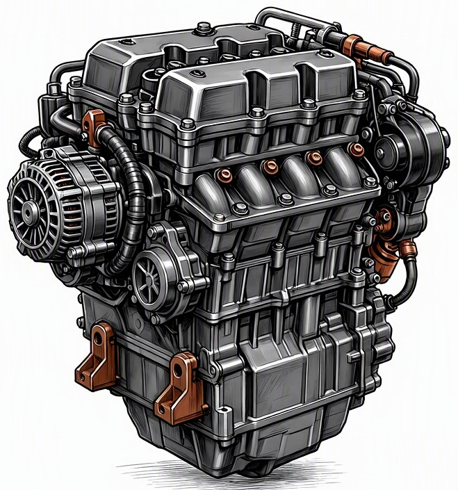
Problem Overview & Engine Systems
Engine wiring harness insulation cracking from heat is a prevalent degradation mechanism impacting the reliability and functionality of internal combustion engines. This condition arises from the prolonged exposure of polymeric insulation materials to elevated temperatures within the engine compartment, leading to a molecular alteration process known as thermal aging or embrittlement. Over time, the insulating properties of the wire jackets diminish, causing them to lose elasticity, harden, and ultimately crack. This exposes the underlying copper conductors to the environment, creating potential for intermittent or permanent electrical faults such as short circuits to ground or power, open circuits, or signal crosstalk due to compromised dielectric strength.
This malfunction directly affects virtually all engine systems that rely on electrical signals and power. The Engine Control Unit (ECU), being the central nervous system of modern engines, is critically dependent on an intact wiring harness. Specific engine systems, blocks, or assemblies where this issue frequently manifests include:
- Fuel Management System: Wiring to fuel injectors, fuel pressure sensors, fuel pump control modules, and oxygen sensors (O2 sensors).
- Ignition System: Circuits for ignition coils, spark plugs (via coils), crankshaft position sensors (CKP), and camshaft position sensors (CMP).
- Emissions Control System: Wiring to Exhaust Gas Recirculation (EGR) valves, catalytic converter temperature sensors, and evaporative emissions (EVAP) system solenoids.
- Cooling System: Electrical connections for Engine Coolant Temperature (ECT) sensors, radiator fan motors and relays.
- Forced Induction Systems: Control circuits for turbocharger wastegates, boost pressure sensors, and supercharger clutches.
- Valvetrain: Wiring to Variable Valve Timing (VVT) or Variable Cam Timing (VCT) solenoids and sensors.
- Sensor & Actuator Circuits: Throttle Position Sensors (TPS), Manifold Absolute Pressure (MAP) sensors, Mass Air Flow (MAF) sensors, idle air control valves (IACV), and knock sensors.
Internal components directly affected are the copper conductors themselves, the terminal pins within connectors, and the integrity of the overall electrical signal path, leading to incorrect data transmission or power delivery.
Common Symptoms
- Primary Signs:
- Check Engine Light (CEL) or Malfunction Indicator Lamp (MIL) illumination, often accompanied by specific Diagnostic Trouble Codes (DTCs) related to circuit performance (e.g., P0XXX, P1XXX codes pertaining to sensor circuits, misfires, or control module communication).
- Intermittent or persistent specific engine noises such as engine stuttering, excessive vibration from misfires, or abnormal relay clicking sounds if relays are affected by erratic signals.
- No direct exhaust smoke color change unless severe misfires cause unburnt fuel in the exhaust (black smoke) or prolonged rich conditions.
- Engine Behavior Changes:
- Engine Misfires: Resulting from intermittent or complete loss of signal to ignition coils or fuel injectors. This can lead to rough idling and loss of power.
- Power Loss/Reduced Performance: The engine may enter “limp-home mode” to prevent further damage, resulting in significantly reduced engine output, poor acceleration, and limited RPMs.
- Rough Running/Fluctuating Idle Speed: Caused by inaccurate sensor readings (e.g., MAF, MAP, ECT, TPS) or erratic control of actuators, leading to unstable fuel-air mixture control.
- Failure to Start/Cranking No Start: If critical sensor signals (e.g., crankshaft or camshaft position) or power to primary actuators (fuel pump, ignition system) are lost.
- Intermittent Electrical Gremlins: Unexpected activation or deactivation of various components, erratic gauge readings, or sudden changes in engine characteristics.
- Increased Fuel Consumption: Engine running rich due to incorrect sensor data causing the ECU to compensate excessively.
Root Causes & Failure Mechanisms
- Thermal Cycling and Prolonged High Temperatures: The primary root cause is the exposure of polymeric insulation materials to recurrent cycles of heating and cooling, alongside sustained high temperatures inherent in modern, often compact, and highly shrouded engine compartments. Areas near exhaust manifolds, turbochargers, and EGR systems are particularly vulnerable. This constant thermal stress accelerates material degradation.
- Material Degradation (Oxidation & Embrittlement): Over time, the chemical structure of the polymeric insulation (e.g., PVC, XLPE, TPE) undergoes oxidation and cross-linking or depolymerization due to heat. This process causes the material to lose its plasticizers, become brittle, harden, and lose its original flexibility and dielectric strength.
- Chemical Exposure: Contamination from engine fluids such as oil, coolant, fuel, or even aggressive cleaning agents can chemically attack and degrade certain types of insulation materials, compromising their integrity and accelerating thermal breakdown, especially if the insulation is not specified for chemical resistance.
- Mechanical Stress and Vibration: Once the insulation becomes brittle, normal engine vibrations, chafing against sharp edges, inadequate strain relief in harness routing, or previous improper repairs can easily cause the now fragile insulation to crack and flake away, exposing the conductors.
- Manufacturing Defects and Substandard Material Selection: In some instances, original equipment manufacturers (OEMs) may have specified or utilized insulation materials that were not adequately rated for the specific thermal and chemical environment of a particular engine bay, leading to premature failure in certain vehicle models or production runs.
- Age and Mileage: The cumulative effect of years of operation, thousands of thermal cycles, and accumulated mileage contribute to general material fatigue and degradation of the wiring harness insulation.
How to Diagnose and Troubleshoot
Diagnosing wiring harness insulation cracking requires a systematic approach, combining diagnostic tools with meticulous visual and tactile inspections.
- Initial Scan & DTC Analysis: Connect an OBD-II scanner or OEM-specific diagnostic tool to retrieve all stored, pending, and history DTCs. Pay close attention to circuit-related codes (e.g., P01XX sensor circuit malfunction, P03XX misfire detection circuit, P06XX ECU/PCM internal fault), as these often point directly to wiring issues. Note freeze-frame data.
- Visual Inspection (Power Off, Engine Cold):
- Disconnect the battery’s negative terminal to prevent accidental shorts.
- Carefully inspect the entire engine wiring harness, paying critical attention to sections routed near intense heat sources (exhaust components, turbochargers, EGR valves), tight bends, areas prone to vibration or chafing, and where the harness enters or exits components.
- Look for visible signs of damage: cracks, brittle sections, melted insulation, exposed conductors, signs of rodent damage, or areas where zip ties or clamps may have overtightened.
- Gently flex suspected sections of the harness. If the insulation is thermally degraded, it will often audibly crackle, flake, or crumble under light manipulation.
- Inspect all connectors for signs of corrosion, bent or pushed-out pins, or heat discoloration.
- Wiggle Test (Engine Running/Key On, Engine Off):
- With the engine running (or key in the ON position for sensor circuits), gently wiggle, bend, and tap sections of the harness, especially those identified as suspicious.
- Observe for changes in engine behavior (RPM fluctuations, misfires, stalling, changes in exhaust note) or monitor live data on the OBD-II scanner for intermittent sensor dropouts or erratic readings.
- Multimeter Testing:
- Continuity Test: Using a digital multimeter (DMM) set to resistance or continuity mode, test individual wires within the suspected harness section from end to end (e.g., from sensor connector to ECU connector) to identify open circuits.
- Resistance Test: Measure the resistance of individual wires. High resistance readings indicate compromised conductors. Compare to specifications or known good circuits.
- Voltage Drop Test: Conduct a voltage drop test across sections of the harness under load. Excessive voltage drop indicates high resistance in the wire or connection, which can be caused by damaged conductors or compromised terminals.
- Short to Ground/Power Test: With components disconnected at both ends of the harness, test for continuity between individual wires and chassis ground, or between adjacent wires, to identify short circuits.
- Oscilloscope Analysis: For intermittent signal issues that are difficult to pinpoint with a DMM, an oscilloscope is invaluable. Monitor critical sensor waveforms (e.g., CKP, CMP, O2 sensor, injector pulse) while performing a wiggle test. Look for signal dropouts, excessive noise, or erratic patterns that coincide with manipulation of the harness.
- Endoscope/Borescope (Optional): For deeply routed or inaccessible sections of the harness, an endoscope can provide visual access without extensive disassembly.
Recommended Repairs and Solutions
The approach to repair depends on the extent and location of the insulation cracking. Safety is paramount due to the potential for fire and loss of vehicle control.
- Localized Harness Repair:
- For minor, isolated damage involving one or two wires in a confined section, a professional repair can be performed. This involves cutting out the damaged wire section and splicing in a new piece of automotive-grade wire of the correct gauge and material (e.g., GXL or TXL with XLPE insulation, or higher-rated silicone-jacketed wire for extreme heat zones).
- Use appropriate crimp connectors (e.g., butt splices with adhesive-lined heat shrink tubing) for mechanical strength and environmental sealing. Soldering is generally discouraged in high-vibration automotive environments unless OEM repair procedures specifically permit or mandate it, and then only with proper strain relief.
- Ensure the repaired section is routed away from heat sources and secured properly to prevent future chafing or stress.
- Sectional Harness Replacement (Pigtails):
- If a larger segment or multiple wires within a specific branch of the harness are severely compromised, pre-made repair sections (pigtails with new connectors) can be spliced in. This is common for sensor or actuator connectors where the wires immediately adjacent to the connector are damaged.
- Always follow OEM splicing recommendations and use high-quality, weather-sealed connectors and wiring.
- Complete Engine Harness Replacement:
- For extensive, widespread damage throughout a significant portion of the engine harness, or if critical multi-pin connectors are severely compromised, a full engine wiring harness replacement is often the most reliable, though labor-intensive, solution. This ensures all potential failure points are addressed and restores the electrical system to OEM specifications.
- This procedure typically involves removal of various engine components for access, careful routing of the new harness, and reconnection to all sensors, actuators, and the ECU.
- Component Replacement: Any sensors, actuators, or electronic control modules (e.g., ECU) that may have been damaged by short circuits, open circuits, or voltage spikes originating from the harness issue will also need replacement. Verify the functionality of these components after harness repair or replacement.
Driving Safety Risk Factors:
- Fire Hazard: Exposed conductors can short circuit, generating intense heat and potentially igniting flammable fluids (fuel, oil) or materials within the engine bay.
- Loss of Vehicle Control: Failure of critical sensors (e.g., CKP, CMP) can lead to unexpected engine shutdown at speed, resulting in loss of power steering and braking assist, posing a severe safety risk.
- Electrical System Damage: Short circuits can cause cascading damage to expensive electronic control modules (ECU, BCM, TCM), significantly increasing repair costs.
- Unreliable Operation: Intermittent faults make the vehicle unpredictable and unreliable, potentially stranding the driver or causing dangerous situations on the road.
Maintenance Recommendations
Preventing engine wiring harness insulation cracking primarily revolves around reducing thermal and mechanical stress, alongside vigilant inspection.
- Regular Visual Inspections: During routine service intervals (e.g., oil changes, tune-ups, tire rotations), visually inspect accessible portions of the engine wiring harness. Pay close attention to areas near heat sources (exhaust, turbocharger), sharp edges, and pinch points. Look for any signs of hardening, cracking, discoloration, or chafing.
- Prompt Fluid Leak Repair: Address any engine oil, coolant, or fuel leaks immediately. Petroleum-based fluids and some coolants can degrade certain types of wire insulation, making them more susceptible to thermal damage.
- Proper Harness Routing and Securing: After any engine work or component replacement, ensure that all wiring clips, ties, and loom protectors are correctly reinstalled. The harness should be routed according to OEM specifications, away from direct heat sources and moving parts, with adequate slack for vibration but not excessive to cause chafing.
- Avoid Unnecessary Aftermarket Modifications: Be cautious with aftermarket modifications that can increase engine bay temperatures (e.g., some exhaust systems) or require additional wiring, especially if not professionally installed or properly routed with high-temperature-rated materials.
- Use High-Quality Repair Materials: If a wire repair is necessary, always use automotive-grade wiring (e.g., GXL or TXL wire with XLPE insulation) rated for high temperatures and appropriate for the specific application. Utilize adhesive-lined heat shrink tubing for environmental protection and proper crimp connectors.
- Rodent Prevention: In areas prone to rodent activity, consider using commercially available rodent deterrent sprays or tapes designed for engine bays, as rodent damage can compound thermal degradation issues.
- Monitor Engine Operating Temperatures: Ensure the engine’s cooling system is operating optimally to prevent consistently elevated engine bay temperatures. Overheating can accelerate insulation degradation.
