
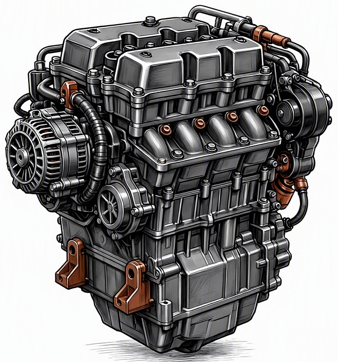
Problem Overview & Engine Systems
An Oxygen Sensor (O2S) heater element circuit fault refers to a diagnostic trouble code (DTC) triggered by the Powertrain Control Module (PCM) when it detects an electrical anomaly within the heating circuit of an oxygen sensor. Modern zirconia-based oxygen sensors require a specific operating temperature, typically 600-800°C, to function accurately and efficiently. This optimal temperature enables the sensor’s zirconia electrolyte to become conductive, allowing it to generate a voltage signal proportional to the oxygen content in the exhaust gas relative to ambient air. To achieve this temperature rapidly during cold starts and maintain it during low exhaust gas flow conditions, a dedicated internal heating element is integrated into the sensor.
This fault primarily belongs to the Emissions Control System and is directly governed by the Engine Management System (EMS) / Powertrain Control Module (PCM). The PCM supplies power (12V) and controls the ground side of the heater circuit (often via a Pulse-Width Modulation, PWM signal) to regulate the heater’s operation. Internal components directly affected include the oxygen sensor’s integrated ceramic heating element, its associated electrical wiring harness, the sensor connector, and the PCM’s internal driver circuit responsible for the heater control. A malfunction in this circuit means the O2 sensor cannot reach or maintain its optimal operating temperature, forcing the PCM to operate in open-loop mode for longer periods or rely on default fuel maps, thereby compromising precise air-fuel ratio (AFR) control and emissions efficiency.
Common Symptoms
- Primary Signs:
- Check Engine Light (CEL) / Malfunction Indicator Lamp (MIL) illuminated on the dashboard.
- Storage of specific Diagnostic Trouble Codes (DTCs) related to O2 sensor heater circuits, such as P0030 (Heater Control Circuit Bank 1 Sensor 1), P0031 (Heater Control Circuit Low), P0032 (Heater Control Circuit High), P0036 (Heater Control Circuit Bank 1 Sensor 2), P0050 (Heater Control Circuit Bank 2 Sensor 1), and similar codes for other sensor banks and positions.
- No specific unusual noises or exhaust smoke directly attributable to this fault.
- Engine Behavior Changes:
- Increased Fuel Consumption: The most common behavioral change, as the PCM operates in open-loop mode for extended durations or uses a richer default fuel map to ensure drivability when accurate O2 sensor data is unavailable.
- Elevated Emissions / Failed Emissions Test: Due to suboptimal air-fuel ratio control, leading to higher levels of unburnt hydrocarbons (HC), carbon monoxide (CO), and nitrogen oxides (NOx) in the exhaust.
- Marginal Performance Degradation: While typically not severe, improper AFR control can lead to slight reductions in engine power or responsiveness under certain driving conditions.
- Rough Idle or Hesitation: Less common, but possible if the sensor provides consistently incorrect or absent data, leading to a significantly skewed AFR.
- Potential Catalytic Converter Damage: Prolonged operation with an excessively rich or lean air-fuel mixture due to the faulty sensor can lead to overheating, fouling, or premature degradation of the catalytic converter, an expensive component.
Root Causes & Failure Mechanisms
- Open Circuit in Heater Element: The most prevalent cause. The thin resistance wire or ceramic heating element inside the oxygen sensor can break due to repeated thermal cycling (expansion and contraction), mechanical vibration, or manufacturing defects. This results in infinite resistance across the heater circuit, preventing current flow and heat generation.
- Short Circuit in Heater Element or Wiring: Less common, but can occur if the heating element’s internal insulation degrades, causing a short within the element itself, or if the external wiring insulation chafes and contacts a ground or power source. A short circuit typically draws excessive current, potentially blowing a fuse or damaging the PCM driver circuit.
- Wiring Harness Damage: Physical damage to the oxygen sensor’s electrical wiring harness is a frequent culprit. This can include chafing against sharp edges, exposure to excessive heat causing insulation breakdown, corrosion at splices, or rodent damage (chewed wires). Such damage can create an open circuit, a short to ground, or a short to power.
- Blown Fuse: The heater circuit for one or more oxygen sensors is often protected by a fuse. A short circuit within the heater element or wiring, or an overcurrent condition, can cause this fuse to blow, interrupting power to the heater.
- Faulty O2 Sensor Connector: Corrosion, bent pins, pushed-out terminals, or a loose connection at the electrical connector can interrupt the heater circuit’s continuity, leading to an open circuit. Water intrusion or environmental contaminants can accelerate connector degradation.
- Powertrain Control Module (PCM) Internal Fault: Although less common than sensor or wiring issues, the PCM’s internal driver transistor or relay responsible for controlling the O2 sensor heater circuit can fail. This prevents the PCM from supplying power or ground to the heater, even if the external wiring and sensor are intact.
How to Diagnose and Troubleshoot
Diagnosing an oxygen sensor heater element circuit fault requires a systematic approach using specialized tools:
- Retrieve Diagnostic Trouble Codes (DTCs) and Freeze Frame Data:
- Utilize an OBD2 scanner to read all stored DTCs. Confirm the presence of heater circuit codes (e.g., P003X, P005X).
- Analyze Freeze Frame Data. This snapshot of engine parameters at the moment the fault was set can provide critical clues regarding engine temperature, load, and speed, which helps understand the conditions under which the heater failed.
- Visual Inspection:
- Begin with a thorough visual inspection of the suspect oxygen sensor’s wiring harness from the sensor itself all the way to its connection point at the main engine harness. Look for signs of chafing, cuts, burns, melted insulation, or rodent damage.
- Inspect the electrical connector at the O2 sensor for corrosion, bent pins, loose terminals, or signs of water intrusion.
- Locate the fuse box (refer to vehicle-specific wiring diagrams) and visually inspect the fuse(s) for the O2 sensor heater circuit. A blown fuse will show a broken filament.
- Electrical System Checks with a Multimeter:
- Heater Element Resistance Test: Disconnect the oxygen sensor. Identify the two heater wires at the sensor side of the connector (typically two wires of the same color, often white or black for a 4-wire sensor). Use a digital multimeter (DMM) set to Ohms to measure the resistance across these two pins. A healthy heater element usually has a resistance between 2 to 10 Ohms (consult service manual for specific values). An “OL” or infinite reading indicates an open circuit, confirming a failed heater element inside the sensor. A reading significantly lower than specified could indicate a short.
- Power Supply Test: With the ignition ON (engine OFF), use the DMM to measure voltage at the vehicle side of the O2 sensor connector, specifically on the power supply wire for the heater circuit (often 12V). Compare to battery voltage. Lack of voltage indicates an issue with the power supply (e.g., blown fuse, wiring break, PCM fault).
- Ground Circuit Continuity Test: For PCM-controlled ground circuits, disconnect the PCM (if safe and instructed by service manual) and check for continuity between the heater ground pin at the O2 sensor connector and the PCM ground pin, or a known good engine ground. This verifies the integrity of the ground wire. For circuits directly grounded to the chassis, verify continuity to chassis ground.
- Current Draw Test (Advanced): Using an amp clamp connected to a DMM, measure the current flowing through the heater circuit with the engine running and the sensor heating. Compare to manufacturer specifications. Abnormal current draw (too high or too low) can indicate a problem.
- Wiring Diagram Consultation: Always refer to the vehicle manufacturer’s specific wiring diagrams to accurately identify wire colors, pin assignments, power sources, and ground paths for the oxygen sensor heater circuit. This is crucial for correct diagnosis.
Recommended Repairs and Solutions
The resolution for an oxygen sensor heater element circuit fault largely depends on the specific root cause identified during diagnosis:
- Oxygen Sensor Replacement: This is the most common repair. If diagnostic tests confirm an open circuit (infinite resistance) or incorrect resistance within the sensor’s heater element, the entire oxygen sensor must be replaced. It is crucial to replace it with a high-quality, OEM-specification sensor to ensure proper function and longevity. Attempting to repair the internal heater element is not feasible. This constitutes a component replacement scale repair.
- Wiring Harness Repair/Replacement: If the fault is traced to damaged wiring (chafing, cuts, rodent damage), the affected section of the wiring harness must be repaired. This involves carefully splicing in new wire sections using appropriate crimp connectors or solder and heat-shrink tubing to ensure electrical integrity and protection against environmental elements. If the damage is extensive or involves the connector itself, a pigtail harness or complete sensor connector replacement may be necessary.
- Fuse Replacement: If a blown fuse is identified, replace it with a new fuse of the exact specified amperage rating. It is important to remember that a fuse blows for a reason (typically an overcurrent from a short circuit). If the fuse blows again immediately or shortly after replacement, a deeper investigation for a short in the wiring or heater element is required.
- PCM/ECM Repair or Replacement (Rare): In the rare instance where all wiring, fuses, and the O2 sensor itself test good, but the PCM is confirmed not to be providing power or ground control to the heater circuit, the PCM itself may be faulty. This is a complex and expensive repair, often requiring specialist diagnosis, replacement, and reprogramming by a dealership or a specialized automotive electronics repair facility.
Driving Safety Risk Factors: Generally, an oxygen sensor heater circuit fault does not pose an immediate, direct safety risk to vehicle occupants. The primary risks are environmental (increased emissions), financial (reduced fuel economy, potential for expensive catalytic converter damage due to prolonged incorrect AFR), and regulatory (failure to pass emissions inspections). While the vehicle is typically drivable, prolonged operation with a significantly incorrect air-fuel mixture should be avoided to prevent damage to expensive exhaust after-treatment components like the catalytic converter.
Maintenance Recommendations
Preventing oxygen sensor heater element circuit faults focuses primarily on electrical system integrity and proactive inspection:
- Regular Visual Inspections: During routine service intervals (e.g., oil changes, tire rotations), incorporate a visual inspection of the oxygen sensor wiring harnesses. Pay particular attention to areas where wires might be exposed to extreme heat, vibration, road debris, or where they pass near sharp edges. Look for signs of chafing, melting, cracking, or any evidence of rodent activity.
- Prompt Diagnostic Attention: Never ignore an illuminated Check Engine Light. Have the vehicle diagnosed promptly by a qualified technician. Early detection of a heater circuit fault can prevent secondary damage to the catalytic converter or other emissions components.
- Use Quality Replacement Parts: When an oxygen sensor needs replacement for any reason, always opt for OEM-quality sensors. Cheaper aftermarket sensors may have inferior heater elements or less precise internal components, leading to premature failure or inaccurate readings.
- Avoid Contaminants: Be mindful of substances that can contaminate oxygen sensors. These include leaded fuels (for older vehicles), silicone-based sealants (especially those containing RTV) used near the exhaust, and engine coolant leaks that might reach the exhaust system. These contaminants can foul the sensor’s sensing element and potentially degrade the heater element’s insulation.
- Maintain Electrical System Health: Ensure the vehicle’s battery and charging system are in good working order. Stable voltage and current supply prevent unnecessary electrical stress on components, including the O2 sensor heater circuit.
- No Specific Fluid Choices or Service Intervals: Unlike engine mechanical issues, this particular fault is not directly influenced by engine oil choice, coolant type, or fuel octane. Its prevention is almost exclusively related to electrical and mechanical integrity.
