
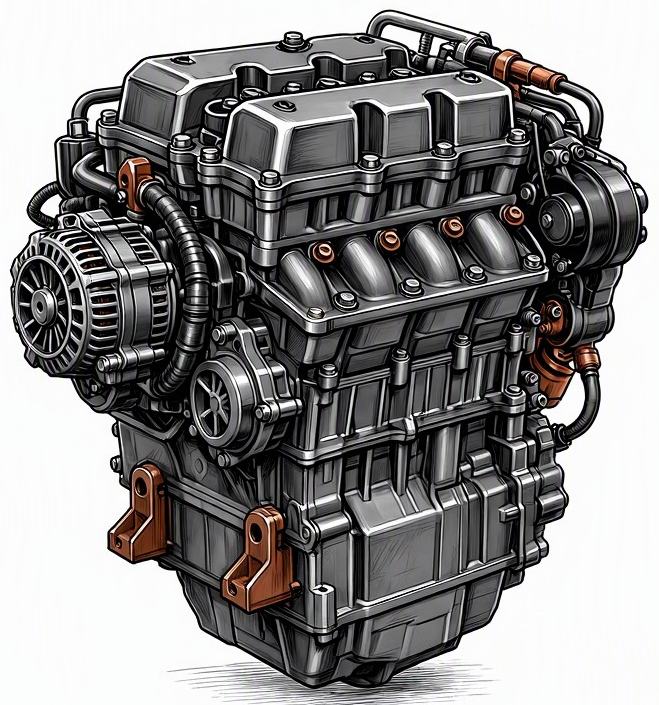
Problem Overview & Engine Systems
Manifold Absolute Pressure (MAP) sensor failure represents a critical malfunction within an internal combustion engine’s Engine Management System (EMS), specifically impacting the air intake and fuel delivery subsystems. The MAP sensor is a crucial transducer, typically a piezoresistive silicon diaphragm device, that measures the absolute pressure within the engine’s intake manifold. This reading, indicative of engine load and ambient barometric pressure, is transmitted as a varying voltage signal to the Engine Control Module (ECM) or Powertrain Control Module (PCM). The ECM utilizes this data, often in conjunction with Intake Air Temperature (IAT) sensor input, to calculate air density and consequently determine appropriate fuel injector pulse width, ignition timing advance, and in some applications, Exhaust Gas Recirculation (EGR) valve operation or turbocharger boost control. A malfunctioning MAP sensor provides erroneous pressure data to the ECM, leading to incorrect calculations for air mass, resulting in either an overly rich or lean air-fuel mixture. While the sensor itself is a self-contained unit, its failure directly impacts the operational parameters of the fuel injection system, ignition system, and emissions control components, including catalytic converter efficiency and longevity due to maladjusted exhaust gas composition. No internal engine components like cylinder block or valvetrain are directly physically affected by the sensor failure, but their performance and long-term health can be severely compromised by the resulting chronic combustion inefficiencies.
Common Symptoms
- Primary Signs: Illumination of the Check Engine Light (CEL) on the dashboard, typically accompanied by specific Diagnostic Trouble Codes (DTCs) ranging from P0105 to P0109, indicating issues with the MAP sensor circuit or performance. In severe cases of a rich mixture, excessive black smoke may be visible from the exhaust tailpipe, indicating unburnt fuel. A persistent fuel odor can also be present. Conversely, a consistently lean condition can lead to engine overheating and, in extreme cases, pre-ignition or detonation.
- Engine Behavior Changes: The vehicle may exhibit a range of performance degradation, including rough idle, engine hesitation or stalling, significant loss of engine power and acceleration, and a noticeable decrease in fuel economy. Misfires can occur across multiple cylinders, especially under load, due to incorrect fuel delivery. Starting difficulties, particularly during cold starts or after prolonged engine operation (hot start issues), are common. In advanced stages of failure, the ECM may enter a “limp home” mode to protect the engine, severely restricting performance and vehicle speed.
Root Causes & Failure Mechanisms
- Electrical Degradation: This is a prevalent cause, encompassing internal failure of the sensor’s piezoresistive element or its signal conditioning circuitry, often due to repeated thermal cycling or manufacturing defects. External electrical issues include corrosion or contamination within the sensor connector terminals, an open or short circuit within the sensor’s wiring harness, or intermittent loss of ground or reference voltage supplied by the ECM/PCM.
- Environmental Contamination and Physical Damage: The MAP sensor is often exposed to the intake manifold environment. Oil vapor and particulate matter from the Positive Crankcase Ventilation (PCV) system can accumulate on the sensing element, fouling it and impeding accurate pressure readings. Water ingress, particularly in sensors exposed to the elements or located in areas prone to splashes, can cause internal short circuits or corrosion. Physical damage due to engine vibration, improper installation, or external impact can lead to cracks in the sensor housing or damage to its delicate internal components.
- Vacuum Line Integrity Issues (Older Designs): For MAP sensors that connect to the intake manifold via an external vacuum hose, degradation of this hose is a critical failure point. A cracked, collapsed, pinched, or disconnected vacuum line will prevent the manifold pressure from accurately reaching the sensor, leading to incorrect readings despite a functional sensor.
- ECM/PCM Malfunction: While less common than sensor failure itself, a faulty ECM/PCM that fails to provide the correct 5-volt reference signal or adequate ground to the MAP sensor, or improperly interprets its signal, can present symptoms identical to a sensor failure. This highlights the importance of comprehensive electrical diagnostics.
How to Diagnose and Troubleshoot
Diagnosis of a failed MAP sensor requires a systematic approach leveraging specific diagnostic tools:
- Preliminary Visual Inspection: Begin by visually inspecting the MAP sensor itself, its electrical connector, and the associated wiring harness for any obvious signs of damage, fraying, corrosion, or contamination. If applicable (for external sensors), inspect the vacuum hose connecting the sensor to the intake manifold for cracks, kinks, or disconnections. Ensure the sensor is securely mounted.
- OBD-II Scan and DTC Analysis: Connect an OBD-II diagnostic scanner to retrieve any stored Diagnostic Trouble Codes (DTCs). MAP sensor-related codes typically fall within the P0105 to P0109 range. Analyze freeze frame data, which captures engine parameters at the moment the DTC was set, to identify operating conditions (engine RPM, load, temperature) that correlate with the malfunction.
- Live Data Monitoring: With the scanner still connected, access live data streams. Monitor the MAP sensor voltage and/or absolute pressure reading with the Key On, Engine Off (KOEO). At KOEO, the MAP sensor should display a reading very close to the ambient barometric pressure (typically 4.5-5.0 V or ~100 kPa / ~29.5 inHg at sea level, decreasing with altitude). Start the engine and observe the MAP reading at idle (should drop significantly, e.g., to 0.7-1.5 V or ~20-40 kPa / ~6-12 inHg, indicating manifold vacuum) and under varying engine loads and RPMs. Look for erratic fluctuations, frozen values, or readings that do not correlate with engine vacuum/load changes. A sensor stuck at a high voltage/pressure reading suggests an open circuit or constant high pressure, while a consistently low reading may indicate a short or constant high vacuum.
- Multimeter Testing of Electrical Circuit: Disconnect the MAP sensor connector. Using a digital multimeter (DMM), verify the 5-volt reference voltage from the ECM/PCM to the sensor (typically one wire). Check for a stable ground signal (typically another wire). Then, backprobe the signal wire with the sensor connected and the engine running, observing the voltage output. With a hand-held vacuum pump (if an external sensor with a port), apply varying levels of vacuum to the sensor while monitoring the signal voltage, which should change proportionally. For intake-mounted sensors, this test is more challenging without a dedicated test port.
- Compare with MAF Sensor (if applicable): On vehicles equipped with both MAF and MAP sensors, comparing their readings can offer insight. A discrepancy where one is plausible and the other is wildly off can indicate the faulty sensor.
- Smoke Test for Vacuum Leaks: While not a direct MAP sensor test, severe vacuum leaks in the intake manifold can cause the MAP sensor to read higher than expected vacuum, leading to incorrect fuel calculations. A smoke test can identify these leaks, which might mimic or exacerbate MAP sensor issues.
Recommended Repairs and Solutions
The primary and most effective solution for a failed MAP sensor is its direct replacement.
- Sensor Replacement: Once confirmed faulty through diagnostic procedures, the MAP sensor should be replaced with a new, high-quality OEM (Original Equipment Manufacturer) or reputable aftermarket unit. Ensure the replacement sensor is specific to the vehicle’s make, model, and engine variant. This is generally a straightforward repair involving disconnecting the electrical connector, removing any retaining bolts or clips, and installing the new sensor.
- Wiring and Connector Repair: If diagnostic steps indicate a fault in the wiring harness or connector, perform precise repairs. This may involve cleaning corroded terminals, repairing or replacing damaged sections of wire, or installing a new connector pigtail. Ensure all connections are secure and weatherproof.
- Vacuum Line Replacement: For older designs utilizing an external vacuum hose, replace any compromised vacuum lines with new, appropriately sized, and heat-resistant hose to ensure an accurate pressure signal reaches the sensor.
- ECM/PCM Diagnosis and Replacement: In very rare cases, if all other components (sensor, wiring, vacuum lines) test perfectly, and the ECM/PCM is not providing the correct reference voltage or processing the signal correctly, the ECM/PCM itself may require reprogramming or replacement. This is typically a last resort after exhaustive component-level testing.
Driving Safety Risk Factors: A faulty MAP sensor poses moderate to high driving safety risks. Inaccurate fuel delivery can lead to sudden and unpredictable engine stalling, particularly at idle or low speeds, or a severe loss of power during acceleration, increasing the risk of accidents. Prolonged operation with a rich or lean condition can lead to accelerated wear and damage to critical engine components (e.g., piston damage from detonation, catalytic converter damage from overheating), escalating repair costs significantly beyond the sensor replacement itself.
Maintenance Recommendations
Preventative maintenance focuses on ensuring the sensor’s operating environment remains clean and its electrical connections are robust.
- Regular PCV System Inspection and Maintenance: A properly functioning Positive Crankcase Ventilation (PCV) system is crucial. A clogged or faulty PCV valve can lead to excessive oil vapor entering the intake manifold, which can contaminate and foul the MAP sensor’s delicate sensing element over time. Inspect and replace the PCV valve and associated hoses according to manufacturer recommendations.
- Intake System Cleanliness: While not a direct maintenance item for the MAP sensor, maintaining overall intake manifold cleanliness helps prevent sensor contamination. For direct-injection engines prone to carbon buildup, periodic intake valve cleaning (e.g., walnut blasting or chemical treatments) can help keep the manifold environment cleaner.
- Wiring Harness and Connector Inspection: During routine service or whenever working in the engine bay, visually inspect the MAP sensor’s wiring harness and connector for any signs of chafing, cracks, rodent damage, or corrosion. Ensure the connector is fully seated and secured. Applying dielectric grease to connectors can help prevent moisture ingress and corrosion.
- Engine Air Filter Replacement: A clean engine air filter ensures that only clean, filtered air enters the intake manifold. While the MAP sensor isn’t directly exposed to the primary incoming air stream, a compromised air filter can allow more contaminants into the intake system, indirectly increasing the risk of sensor fouling. Follow optimal service intervals for air filter replacement.
- Mindful Driving Habits: While less direct, avoiding prolonged periods of excessively rich or lean operation (e.g., ignoring a Check Engine Light) not only protects other engine components but also prevents stressing the EMS as it attempts to compensate for erroneous MAP data.
