
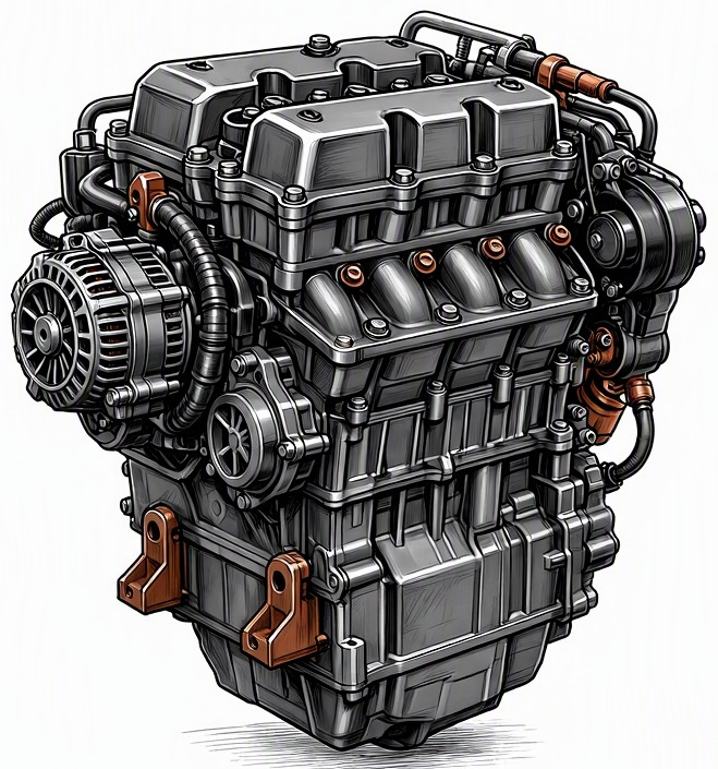
Problem Overview & Engine Systems
The Crankshaft Position Sensor (CKP or CPS) is a critical inductive or Hall-effect transducer that monitors the rotational speed (RPM) and angular position of the engine’s crankshaft. This data is transmitted to the Powertrain Control Module (PCM), also known as the Engine Control Unit (ECU), which utilizes it for precise synchronization of ignition timing, fuel injection pulses, and sometimes variable valve timing (VVT) or cam phasing. A malfunction in the CPS directly compromises the PCM’s ability to accurately determine piston position relative to Top Dead Center (TDC) for cylinder #1, leading to a cascade of operational deficiencies. The sensor typically interfaces with a multi-tooth reluctor wheel (also known as a tone ring or trigger wheel) mounted on the crankshaft itself, the harmonic balancer, or the flywheel/flexplate. While physically located proximate to the Crankshaft Assembly, the CPS is functionally an integral component of the overarching Engine Management System (EMS). Its failure directly impacts the functionality of the Ignition System (spark timing) and the Fuel Delivery System (injector timing). The internal components directly affected by a malfunction include the sensor’s internal circuitry, its magnetic pole piece (for inductive types) or Hall element, its connecting wiring harness, and potentially the integrity of the reluctor wheel itself.
Common Symptoms
- Primary Signs:
- Illumination of the Check Engine Light (CEL) on the dashboard, often accompanied by diagnostic trouble codes (DTCs) such as P0335 (Crankshaft Position Sensor ‘A’ Circuit) or P0336 (Crankshaft Position Sensor ‘A’ Circuit Range/Performance).
- In some critical failure modes, the engine may exhibit a complete no-start condition, cranking but failing to ignite.
- The tachometer may display erratic readings, drop to zero while the engine is running, or remain at zero during cranking, failing to register engine speed.
- Engine Behavior Changes:
- Extended cranking time before the engine starts, or intermittent failure to start.
- Rough idling or inconsistent idle speed, often fluctuating significantly.
- Engine misfires, which may be intermittent or constant, leading to noticeable vibrations and reduced power.
- Sudden and unpredictable stalling of the engine while driving, at idle, or when coming to a stop.
- Reduced engine power and responsiveness, sometimes resulting in the PCM entering a limp-home mode to prevent further damage.
- Inconsistent or delayed acceleration, with noticeable hesitation or jerking during throttle application.
- Engine may intermittently cut out or completely die at higher speeds, requiring a restart.
Root Causes & Failure Mechanisms
- Electrical System Degradation: Deterioration or damage to the sensor’s wiring harness, including frayed wires, exposed conductors, or corrosion within the connector terminals. This can lead to intermittent signal loss, short circuits, or an open circuit.
- Internal Sensor Component Failure: Over time, the internal electronics of the CPS (e.g., Hall effect transducer, permanent magnet, coil windings) can degrade due to continuous exposure to engine heat cycling, vibration, and electromagnetic interference. This leads to a weak, erratic, or absent signal output.
- Physical Damage or Contamination: The sensor itself may suffer physical impact from road debris, contact with other engine components if improperly mounted, or exposure to excessive engine oil, coolant, or road salt, which can degrade its housing or internal components.
- Reluctor Wheel Anomalies: Damage to the crankshaft-mounted reluctor wheel (e.g., bent teeth, missing teeth, excessive buildup of ferromagnetic debris) can alter the signal perceived by the sensor, leading to incorrect timing data. Excessive crankshaft end-play or main bearing wear can also alter the gap between the sensor and reluctor wheel, affecting signal integrity.
- Thermal Stress and Vibration: Located often in close proximity to the engine block or exhaust components, the sensor is continuously subjected to significant thermal cycling and engine vibrations. These environmental factors contribute to fatigue and eventual failure of internal electrical connections or the sensor housing.
How to Diagnose and Troubleshoot
Diagnosing a CPS malfunction requires a systematic approach utilizing specialized tools:
- Retrieve Diagnostic Trouble Codes (DTCs): Connect an OBD-II scanner to the vehicle’s Data Link Connector (DLC). Note any present, pending, or historical DTCs, particularly P0335, P0336, and any manufacturer-specific codes related to the crankshaft position sensor.
- Visual Inspection: Disconnect the vehicle’s battery. Locate the CPS (typically mounted near the crankshaft pulley, bell housing, or oil pan). Visually inspect the sensor, its mounting, and the entire length of its wiring harness for any signs of physical damage, chafing, corrosion at the connector, or oil/fluid saturation. If accessible, inspect the reluctor wheel for damage or debris.
- Live Data Analysis (OBD-II Scanner): With the engine cranking or running (if possible), monitor the “Engine RPM” or “Crankshaft Position Sensor” parameter in the scanner’s live data stream. A properly functioning sensor will show a consistent RPM reading; an erratic, intermittent, or absent reading (0 RPM while cranking) indicates a problem. Simultaneously monitor the “Camshaft Position Sensor (CMP)” signal; discrepancies between CKP and CMP can indicate a CKP issue or a timing problem.
- Multimeter Testing:
- Voltage Supply: With the ignition ON (engine OFF), test for proper reference voltage (typically 5V or 12V) at the sensor’s power supply terminal in the connector, relative to ground.
- Ground Circuit: Verify a strong ground signal at the sensor’s ground terminal.
- Sensor Resistance (Inductive Type): For 2-wire inductive sensors, disconnect the sensor and measure its internal resistance across the terminals. Compare to manufacturer specifications (typically 200-2000 ohms). An open circuit or resistance outside specifications indicates a faulty sensor.
- Signal Wire Continuity/Shorts: Perform continuity tests on the signal wire from the sensor connector back to the PCM connector. Check for shorts to ground or power.
- Oscilloscope Analysis (The Gold Standard): This is the most definitive diagnostic step. Connect a digital storage oscilloscope to the CKP sensor’s signal wire and a reliable ground. While cranking the engine, observe the waveform:
- Inductive Sensor: Expect a sine wave that increases in amplitude and frequency with engine speed.
- Hall-effect Sensor: Expect a clean, consistent square wave with distinct ON/OFF voltage states.
Look for missing pulses, erratic patterns, signal dropouts, excessive noise, or an absence of a signal. Compare the observed waveform to known good patterns for the specific sensor type and vehicle. An abnormal waveform confirms sensor or reluctor wheel issues.
Recommended Repairs and Solutions
The primary repair for a confirmed crankshaft position sensor malfunction typically involves direct component replacement:
- Crankshaft Position Sensor Replacement: Replace the faulty sensor with a new, high-quality OEM or reputable aftermarket unit. Ensure the mounting bolts are torqued to specification and any required air gap (if adjustable) is correctly set according to the service manual.
- Wiring Harness Repair/Replacement: If the diagnosis points to a damaged wiring harness or corroded connector, repair the specific section using appropriate automotive-grade wiring and connectors, or replace the entire sub-harness if damage is extensive.
- Reluctor Wheel Inspection and Repair: If an oscilloscope reveals a distorted signal pattern indicative of reluctor wheel damage (e.g., missing teeth, runout), the reluctor wheel will need to be inspected and potentially replaced. This often requires significant engine disassembly, such as removal of the harmonic balancer or transmission/flywheel, making it a more complex and labor-intensive repair.
- PCM/ECU Diagnosis: In rare cases, if the sensor and wiring test perfectly, but no signal is registered by the PCM, a faulty PCM input circuit or internal processing error may be suspected. This requires advanced diagnostic procedures, potentially involving PCM replacement or reprogramming by a specialist.
Driving Safety Risk Factors: A malfunctioning crankshaft position sensor presents a significant driving safety risk. The unpredictable nature of engine stalling, misfires, or complete failure to start can lead to loss of power steering and power brakes (in vehicles where these are engine-driven), potentially causing loss of control, especially at highway speeds or in heavy traffic. Immediate diagnosis and repair are crucial to prevent serious accidents or dangerous breakdowns.
Maintenance Recommendations
While crankshaft position sensors are not typically considered routine maintenance items, certain practices can contribute to their longevity and prevent premature failure:
- Periodic Visual Inspection: During routine service intervals, such as oil changes or under-hood inspections, visually inspect the CPS and its associated wiring. Look for signs of physical damage, frayed insulation, corrosion on the connector, or excessive oil saturation that could degrade the sensor’s housing or electrical integrity.
- Address Fluid Leaks Promptly: Repair any engine oil, coolant, or power steering fluid leaks in the vicinity of the CPS. Exposure to these fluids can accelerate the degradation of the sensor’s protective housing and internal components.
- Utilize Quality Replacement Parts: If a CPS ever requires replacement, always opt for OEM (Original Equipment Manufacturer) parts or high-quality aftermarket equivalents from trusted brands. Inferior sensors may have a shorter lifespan, provide less accurate signals, or fail prematurely.
- Professional Installation: When replacing the sensor, ensure it is installed correctly, with proper torque applied to mounting bolts and, if applicable, the correct air gap between the sensor tip and the reluctor wheel. Incorrect installation can lead to immediate failure or reduced lifespan.
- Avoid Physical Damage: Be mindful of the sensor’s location when performing other engine repairs or maintenance. Accidental impact or forceful handling can easily damage the sensor.
- Regular Engine Health Checks: Using an OBD-II scanner periodically to check for pending or stored DTCs, even without an illuminated CEL, can sometimes catch intermittent sensor issues before they escalate into full failures.
