
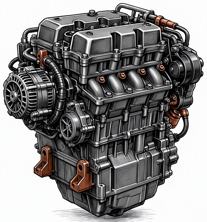
Problem Overview & Engine Systems
A camshaft position sensor (CPS) malfunction represents a critical failure within the engine’s control and timing systems, significantly impacting combustion event orchestration. The CPS is an indispensable component of the engine management system (EMS), specifically belonging to the Valvetrain and Engine Control Unit (ECU) interface assemblies. Its primary function is to monitor the angular position and rotational speed of the camshaft, transmitting this data as an electrical signal to the ECU. This information is vital for the ECU to accurately synchronize fuel injection events with the intake and exhaust valve operation, and in many applications, to precisely time ignition spark delivery relative to crankshaft position. A faulty CPS directly corrupts the ECU’s ability to determine which cylinder is at its compression stroke top dead center (TDC), leading to mis-timed fuel delivery, ignition, or variable valve timing (VVT) adjustments. Internally, direct components affected by this malfunction are primarily the sensor itself and its target (the reluctor wheel or cam phaser tone wheel attached to the camshaft). Indirectly, the entire combustion cycle suffers, affecting fuel injectors, ignition coils, and ultimately the mechanical components of the cylinder block that rely on precise timing for optimal operation.
Common Symptoms
- Primary Signs:
- Check Engine Light (MIL) Illumination: This is almost universally the first and most prominent indicator, often accompanied by diagnostic trouble codes (DTCs) ranging from P0340 to P0349, indicating a circuit malfunction or an implausible signal.
- Extended Cranking: The engine may take significantly longer to start, particularly when cold, as the ECU struggles to establish camshaft-crankshaft synchronization without reliable CPS data.
- Intermittent Stalling: The engine may unexpectedly cut out, especially at idle or low speeds, due to sudden loss of synchronization.
- Engine Behavior Changes:
- Rough Idling or Stumbling: Inaccurate timing information can lead to imprecise fuel delivery and spark timing, causing the engine to run roughly at idle or stumble under light load.
- Reduced Engine Performance: A noticeable decrease in horsepower and torque may occur as the ECU often reverts to a “limp home” mode or a default timing strategy, which is inefficient.
- Misfires: Improper synchronization can cause cylinders to misfire due to fuel being injected at the wrong time or ignition spark occurring out of phase with the compression stroke.
- Poor Fuel Economy: Inefficient combustion due to timing discrepancies directly contributes to increased fuel consumption.
- Failure to Start: In severe cases or with complete sensor failure, the engine may crank but not start at all, as the ECU cannot establish the necessary synchronization to initiate combustion.
Root Causes & Failure Mechanisms
- Electrical Malfunction/Internal Degradation: The most common failure mode involves the internal electronics of the sensor. Over time, exposure to engine heat, vibration, and general operational stress can lead to the breakdown of semiconductor components, solder joints, or the magnetic field generator (for Hall effect sensors) or coil winding (for inductive sensors). This results in an open circuit, short circuit, or a corrupted signal output.
- Wiring Harness Integrity Compromise: The electrical wiring connecting the CPS to the ECU is susceptible to damage. Common issues include insulation chafing against other engine components, rodent damage, corrosion at the connector pins due to moisture ingress, or fatigued wires from engine vibration. A compromised wiring harness can lead to intermittent signal loss, incorrect resistance, or complete circuit failure.
- Reluctor Wheel (Tone Wheel) Damage or Misalignment: The CPS relies on a precisely machined reluctor wheel or cam phaser with specific teeth or windows to generate its signal. Damage from debris, manufacturing defects, or improper installation of valvetrain components can bend, crack, or misalign the reluctor wheel, preventing the sensor from generating an accurate or consistent signal.
- Environmental Contamination: While most CPS units are sealed, prolonged exposure to oil leaks, coolant, or road grime can degrade the sensor’s housing or electrical connector seals, allowing contaminants to ingress and interfere with internal components or electrical connections. Extreme thermal cycling can also accelerate material fatigue.
- Sensor Mounting/Air Gap Issues: The sensor’s ability to accurately read the reluctor wheel depends on a precise air gap. If the sensor is improperly seated, becomes loose due to vibration, or if foreign material accumulates between the sensor tip and the reluctor wheel, the signal strength or accuracy can be compromised.
How to Diagnose and Troubleshoot
Diagnosing a camshaft position sensor malfunction requires a methodical approach using specialized tools:
- Retrieve Diagnostic Trouble Codes (DTCs): Connect an OBD-II scanner to the vehicle’s diagnostic port. Typical CPS-related codes include P0340 (Camshaft Position Sensor Circuit Malfunction – Bank 1 Sensor 1) through P0349. These codes are crucial for pinpointing the general area of the fault.
- Visual Inspection:
- Locate the camshaft position sensor. Visually inspect the sensor for any obvious physical damage, cracks, or signs of oil/coolant contamination.
- Examine the wiring harness connected to the CPS. Look for chafing, cuts, signs of rodent damage, or loose/corroded connectors. Gently tug on the wires near the connector to check for poor pin retention.
- If accessible, inspect the reluctor wheel (target wheel) for bent teeth, cracks, or foreign material accumulation. An endoscope may be necessary for non-intrusive inspection of the reluctor wheel through the sensor bore.
- Electrical Testing (Using a Digital Multimeter – DMM):
- Power and Ground: With the ignition ON (engine OFF), use a DMM to verify proper voltage supply (typically 5V or 12V) and a good ground at the sensor connector. Back-probe the connector to avoid damaging pins.
- Sensor Signal Test: Depending on sensor type (Hall effect or inductive), test procedures vary.
- Hall Effect Sensor: With the ignition ON, back-probe the signal wire. Manually rotate the engine (if possible and safe) or crank it. The DMM should show a toggling voltage (e.g., switching between near 0V and 5V).
- Inductive Sensor: Measure the resistance across the sensor’s signal terminals (with sensor disconnected). A specified resistance range should be found in service manuals. Also, check for AC voltage generation while cranking the engine; an inductive sensor should produce a small AC voltage pulse.
- Continuity Check: With the battery disconnected, use the DMM’s continuity function to check for opens or shorts in the sensor’s wiring harness back to the ECU connector.
- Oscilloscope Waveform Analysis: This is the definitive diagnostic step. Connect an oscilloscope to the CPS signal wire while cranking or running the engine. Observe the signal waveform.
- A good Hall effect sensor will produce a clean, square-wave pattern with consistent high and low voltage states and no dropouts.
- An inductive sensor will produce a sine-wave pattern with consistent amplitude and frequency.
- An erratic signal, flatline, inconsistent amplitude, noise, or dropouts clearly indicate a sensor, wiring, or reluctor wheel issue. Simultaneously monitoring the crankshaft position sensor (CKP) signal provides a comparative reference for synchronization issues.
- ECU/PCM Health Check: While rare for a direct CPS malfunction, ensure there are no other unrelated ECU faults that could indirectly affect sensor processing.
Recommended Repairs and Solutions
The primary repair for a confirmed camshaft position sensor malfunction is the replacement of the faulty sensor unit. This is generally a straightforward component replacement, though accessibility varies significantly between engine designs. For sensors located under valve covers or integrated into timing chain covers, the repair complexity and labor cost will be higher.
- Component Replacement:
- Camshaft Position Sensor: Always replace with an OEM equivalent or a high-quality aftermarket sensor to ensure compatibility and reliability.
- Wiring Harness Repair/Replacement: If the wiring is damaged, perform a precise splice repair using appropriate connectors and heat shrink tubing, or replace the entire section of the harness if damage is extensive.
- Reluctor Wheel Repair/Replacement: If the reluctor wheel is damaged, it typically requires significant disassembly of the valvetrain (e.g., removal of camshafts or timing chain cover) to replace or repair. This is a more extensive and costly repair.
- Repair Scale: Most CPS malfunctions are resolved with simple component replacement of the sensor itself. Only in cases of severe mechanical damage to the reluctor wheel or extensive wiring harness damage does the repair escalate to a more involved procedure. Cylinder head resurfacing or complete engine overhaul are not directly associated with CPS malfunctions unless a collateral catastrophic event occurred.
- Driving Safety Risk Factors: A malfunctioning CPS poses significant driving safety risks. Intermittent stalling, sudden loss of power, or a complete no-start condition can leave a driver stranded or create hazardous situations in traffic. The engine’s unpredictable behavior can lead to loss of control, especially during highway driving or critical maneuvers. Prompt diagnosis and repair are essential.
Maintenance Recommendations
Preventing camshaft position sensor failures primarily involves diligent general engine maintenance and proactive inspection during related service operations:
- Adhere to Manufacturer’s Service Intervals: Regular oil changes with the correct viscosity and specification of engine oil help maintain overall engine health, which indirectly benefits sensor longevity by ensuring a clean operating environment and stable engine temperatures.
- Inspection During Timing System Service: If the vehicle’s timing belt or timing chain requires replacement, this presents an opportune time to inspect the CPS and its associated wiring harness. Given the proximity and accessibility during these procedures, proactively inspecting for wear, damage, or looseness of the sensor and its reluctor wheel can prevent future issues. Consider replacing the CPS as a preventative measure if it’s nearing the high-mileage mark during a timing chain/belt service, especially if it’s difficult to access otherwise.
- Wiring Harness Checks: During routine inspections or other engine bay services, visually examine exposed wiring harnesses, particularly those running close to hot or vibrating components, for any signs of chafing, cracking, or deterioration of insulation. Ensure all connectors are securely latched.
- Use Quality Components for Replacements: When any sensor or engine component is replaced, always opt for OEM (Original Equipment Manufacturer) parts or reputable aftermarket brands. Inferior quality sensors may have shorter lifespans or provide less accurate signals, leading to premature failure.
- Avoid Contaminants: Address any engine oil or coolant leaks promptly. Allowing fluids to continuously bathe electrical connectors or sensor housings can lead to corrosion and premature sensor failure.
- Proper Installation Procedures: If replacing a CPS, ensure it is installed correctly, tightening to specification and verifying the proper air gap (if adjustable), to prevent physical damage or inaccurate readings.
