
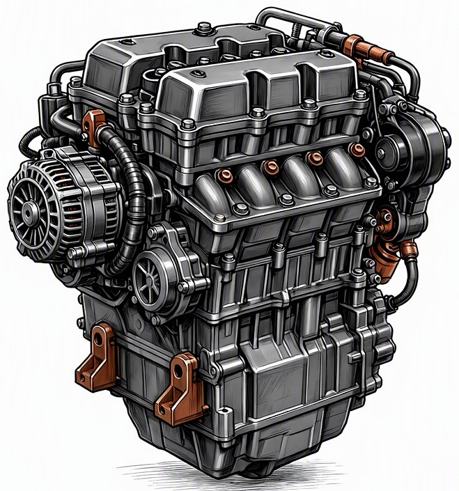
Problem Overview & Engine Systems
Wiring harness corrosion under the hood represents a significant electrical integrity fault that can compromise the operational reliability and diagnostic accuracy of modern internal combustion engines. This phenomenon involves the electrochemical degradation of metallic conductors and terminals within the engine’s wiring harnesses, leading to increased electrical resistance, intermittent connectivity, or complete circuit open/short conditions. Unlike mechanical wear or thermal fatigue, corrosion directly attacks the material’s conductivity, often propagating insidiously within sealed connectors or under wire insulation. While not directly affecting a single mechanical engine block or assembly in the same manner as a worn bearing, its impact is pervasive across virtually every electronically controlled engine system. Specifically, it can severely impair the functionality of the Engine Control Unit (ECU) by distorting or interrupting signals from critical sensors (e.g., Manifold Absolute Pressure – MAP, Mass Air Flow – MAF, Oxygen – O2, Engine Coolant Temperature – ECT, Crankshaft Position, Camshaft Position) and impairing the operation of actuators (e.g., fuel injectors, ignition coils, Variable Valve Timing – VVT solenoids, electronic throttle body motors, cooling fan relays). The direct internal components affected are the copper strands of the wiring itself, the plating on electrical terminals (typically tin, gold, or silver), and the integrity of solder joints within sensors or control modules, all of which depend on pristine electrical conductivity for proper function.
Common Symptoms
- Primary Signs: Illumination of the Check Engine Light (CEL), often accompanied by specific Diagnostic Trouble Codes (DTCs) related to circuit malfunctions (e.g., P0XXX – Sensor Circuit Malfunction, P030X – Misfire Detected). Other warning lights such as ABS, Traction Control, or battery warning lights may illuminate if their respective harnesses are affected. Intermittent no-start conditions, difficulty starting, or complete failure to start. Erratic or inaccurate readings on the instrument cluster (e.g., fluctuating temperature gauge, inaccurate fuel level if wiring to senders is affected).
- Engine Behavior Changes: Engine misfires (random or cylinder-specific), significant power loss or reduced acceleration, rough or fluctuating idle speed, engine surging or bucking, hesitation during acceleration, stalling at idle or low speeds, activation of limp-home mode, poor fuel economy, noticeable changes in transmission shift quality (if transmission control module communication is affected), cooling fan running constantly or not engaging when required, and inaccurate sensor data causing improper fuel mixture leading to rich or lean conditions.
Root Causes & Failure Mechanisms
- Environmental Exposure & Chemical Contamination: Prolonged exposure to moisture, road salt, humidity, and chemical agents such as battery acid vapors, coolant leaks, brake fluid, or harsh engine bay cleaning products. These substances act as electrolytes, accelerating galvanic or crevice corrosion, especially between dissimilar metals used in terminals and wire alloys.
- Physical Damage & Design Flaws: Abrasion of wire insulation due to chafing against engine components, sharp edges, or inadequate loom protection, exposing conductors to the environment. Insufficient sealing of connectors (e.g., degraded rubber gaskets, cracked plastic shells) allows moisture and contaminants to ingress. Poor quality terminal crimps during manufacturing or repair can create points of high resistance that corrode rapidly.
- Thermal Cycling & Age Degradation: Repeated expansion and contraction cycles from extreme under-hood temperatures can compromise the integrity of wire insulation and connector seals, creating micro-fractures. Over time, the plasticizers in wire insulation can migrate, leading to embrittlement and cracking, exposing the underlying conductors. Furthermore, rodent damage, where animals chew through insulation to nest or for calcium, is a significant and unfortunately common cause.
How to Diagnose and Troubleshoot
Diagnosing wiring harness corrosion requires a systematic approach combining visual inspection, electrical testing, and diagnostic scanning.
- Initial Visual Inspection: Begin with a thorough visual inspection of all accessible wiring harnesses and connectors under the hood. Look for tell-tale signs of corrosion such as green, white, or blue powdery deposits on terminals or inside connectors, swelling or cracking of wire insulation, signs of rodent damage, or evidence of fluid leaks that may have contacted wiring. Pay close attention to ground points, sensor connectors, and ECU connections.
- Retrieve Diagnostic Trouble Codes (DTCs): Utilize an OBD-II diagnostic scanner to retrieve any stored DTCs. These codes often provide specific circuit or component fault information (e.g., “Sensor X Circuit Low Input,” “Injector Y Circuit Open”). Freeze frame data should also be analyzed for conditions present when the fault occurred.
- Wiggle Test and Live Data Analysis: With the ignition on and the engine running (if possible), gently manipulate and wiggle suspect wiring harnesses and connectors while monitoring live data streams on the diagnostic scanner or observing engine behavior for intermittent changes. This can reveal loose connections or intermittent opens/shorts caused by corrosion.
- Voltage Drop Test: Use a high-impedance Digital Multimeter (DMM) to perform voltage drop tests across suspect power and ground circuits. A significant voltage drop (typically >50mV for signal wires or >100-200mV for power/ground circuits under load) indicates excessive resistance, often due to corrosion. Test both the power feed and the ground path.
- Continuity and Resistance Testing: Disconnect the battery and individually test suspect wires for continuity and resistance. An ‘open circuit’ or high resistance reading (significantly above 0 ohms for a short run of wire) confirms a fault within that conductor. This is best done by de-pinning connectors or back-probing carefully.
- Back-Probing and Signal Integrity: Carefully back-probe connectors with a DMM or oscilloscope to test voltage and signal integrity at specific pins, comparing readings against manufacturer specifications. This helps determine if the signal is reaching the ECU correctly or if the actuator is receiving proper voltage.
- Pin Tension Test: Utilize specialized pin tension tools to evaluate the retention force of terminals within connectors. Loose pins, often caused by corrosion or repeated connection/disconnection, can lead to intermittent connections.
Recommended Repairs and Solutions
The repair strategy for wiring harness corrosion depends on the severity and extent of the damage.
- Minor Corrosion Cleaning: For localized, light corrosion, carefully clean affected terminals and connectors using specialized electrical contact cleaner and non-abrasive tools (e.g., fiberglass scratch pens, fine brass brushes). After cleaning, apply a thin coat of dielectric grease to prevent future corrosion and improve sealing.
- Terminal and Wire Repair: If individual terminals are heavily corroded, bent, or if a wire is broken, de-pin the affected terminal from the connector housing. Replace the terminal with an OEM-grade equivalent using proper crimping tools. For wire damage, perform a professional splice repair using a solder-and-heat-shrink method with adhesive-lined heat shrink tubing, ensuring an airtight and moisture-resistant seal. Avoid generic butt connectors as they can introduce additional resistance and future corrosion points.
- Connector Replacement: If the plastic connector body is cracked, the internal seals are compromised, or multiple terminals are damaged, the entire connector housing should be replaced. This involves carefully transferring pins or replacing them as needed, ensuring correct pin-out.
- Harness Segment Replacement: For extensive damage to a specific sub-harness (e.g., injector harness, sensor harness) that makes individual wire repair impractical or unreliable, it is more effective and robust to replace the entire segment of the harness with a new OEM part.
- Complete Engine Harness Replacement: In cases of widespread, severe, or inaccessible corrosion throughout the main engine harness, a complete replacement of the engine wiring harness may be the only reliable solution. This is a labor-intensive and costly repair but ensures the full restoration of electrical integrity.
The repair scale can range from a minor spot repair of a single wire to a complete engine harness overhaul. Driving safety risk factors associated with unaddressed wiring harness corrosion include sudden engine stalling, loss of power during critical maneuvers, erratic operation of safety systems (e.g., ABS), and potential for electrical fires due to excessive resistance generating heat within the circuit.
Maintenance Recommendations
Preventing wiring harness corrosion is crucial for long-term engine reliability and involves several proactive measures:
- Regular Visual Inspections: Incorporate routine visual checks of all accessible wiring harnesses and connectors during regular service intervals. Look for signs of chafing, fluid leaks near wiring, and early indications of corrosion.
- Prompt Leak Repair: Address any fluid leaks (coolant, oil, brake fluid, battery acid) immediately. These fluids are often corrosive and can degrade wire insulation and promote corrosion on electrical terminals.
- Strategic Dielectric Grease Application: Apply a small amount of high-quality dielectric grease to critical or exposed electrical connectors during reassembly or preventative maintenance. This forms a protective barrier against moisture and contaminants without impeding electrical flow across terminals.
- Protect Against Rodents: Implement measures to deter rodents from nesting in the engine bay, such as using rodent repellents or ensuring the engine bay is clean and free of nesting materials. Rodent damage is a frequent and severe cause of harness damage.
- Proper Cleaning Practices: When cleaning the engine bay, avoid direct high-pressure washing onto electrical connectors and components. Use appropriate automotive cleaners and ensure components are thoroughly dried afterward.
- Secure and Route Harnesses Correctly: Ensure all wiring harnesses are properly secured in their factory clips and routed away from hot engine components, sharp edges, and pinch points to prevent insulation abrasion.
- Utilize Quality Components: When replacing sensors, actuators, or other electrical components, always use OEM-quality or reputable aftermarket parts that come with robust connectors and quality wire insulation to maintain system integrity.
