
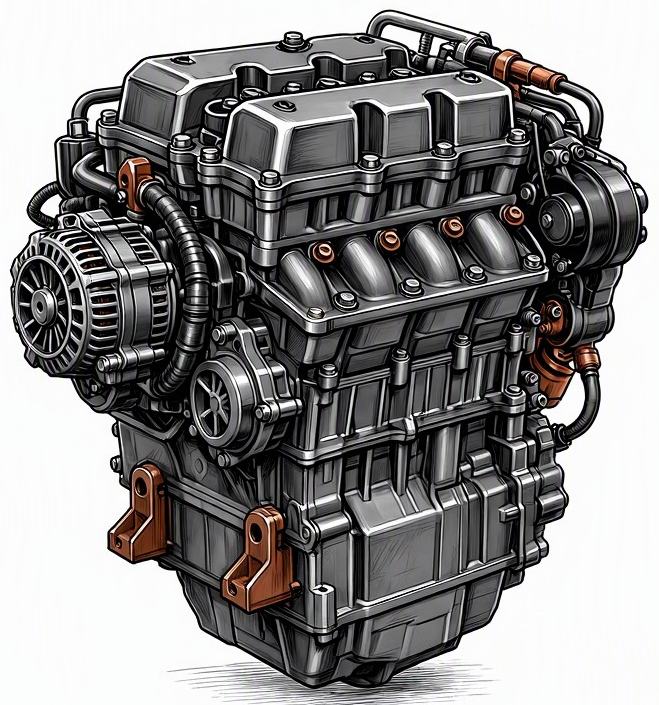
Problem Overview & Engine Systems
Engine Control Unit (ECU) thermal breakdown refers to the degradation or catastrophic failure of the ECU’s internal electronic components due to excessive heat. The ECU, often interchangeably called the Powertrain Control Module (PCM), is the central microcomputer responsible for managing an internal combustion engine’s operation. This malfunction typically involves the failure of semiconductors (e.g., microprocessors, power transistors, voltage regulators), electrolytic capacitors, or solder joints within the unit, whose operational integrity is highly sensitive to temperature extremes. When these components exceed their thermal design limits, their electrical characteristics degrade, leading to erratic operation, intermittent failures, or complete cessation of function.
This critical malfunction directly affects virtually all engine systems, as the ECU is the master controller. Specifically, components and systems directly controlled or monitored by the ECU that become compromised include:
- Fuel System: Fuel injector pulse width and timing, fuel pump relay control, fuel pressure regulation via fuel pump control module.
- Ignition System: Ignition coil dwell time, spark timing, and firing sequence.
- Air Induction & Throttle System: Electronic throttle body (ETC) control, Variable Valve Timing (VVT) / Variable Valve Lift (VVL) actuation, turbocharger/supercharger boost control solenoids.
- Emission Control System: Exhaust Gas Recirculation (EGR) valve control, secondary air injection, evaporative emission (EVAP) system control, oxygen sensor feedback processing.
- Cooling System: Radiator fan activation, coolant temperature sensor signal processing.
- Sensor & Actuator Interface: The ECU processes inputs from manifold absolute pressure (MAP), mass airflow (MAF), crankshaft position (CKP), camshaft position (CMP), engine coolant temperature (ECT), throttle position (TPS), and numerous other sensors, then outputs commands to various actuators. Thermal breakdown disrupts this entire feedback loop.
- Internal ECU Components: Microprocessor cores, memory modules (ROM, RAM, EEPROM), Analog-to-Digital (ADC) converters, Digital-to-Analog (DAC) converters, power output drivers (e.g., H-bridges for solenoids, injector drivers), communication transceivers (CAN, LIN bus), and critical voltage regulation circuits.
Common Symptoms
- Primary Signs:
- Check Engine Light (MIL) Illumination: Often accompanied by numerous or seemingly unrelated Diagnostic Trouble Codes (DTCs), including P06xx series codes (ECU processor faults, internal memory errors), Uxxxx communication codes, or a plethora of system-specific codes.
- No Start / Extended Cranking: Engine cranks but fails to ignite or takes an unusually long time to start.
- Intermittent Operation: Engine stalls unexpectedly, especially after reaching operating temperature or during prolonged driving, and may restart after cooling down.
- Engine Behavior Changes:
- Rough Idle / Stalling: Unstable or fluctuating idle speed, engine often stalls at idle or low speeds.
- Misfires: Random or multiple cylinder misfires, often leading to reduced power and rough running.
- Power Loss / Limp Mode: Significant reduction in engine power, unresponsive throttle, vehicle entering “limp home” mode.
- Erratic Fuel Economy: Unexplained decreases or increases in fuel consumption due to incorrect fuel trim adjustments.
- Abnormal Transmission Shifting: If the ECU integrates Transmission Control Module (TCM) functions, erratic or harsh shifting may occur.
- Cooling Fan Malfunction: Radiator cooling fan either runs continuously or fails to activate when necessary.
- Sensor Reading Discrepancies: Scan tool data stream may show erroneous or frozen sensor values.
Root Causes & Failure Mechanisms
- Excessive Ambient Temperature Exposure: Prolonged operation or installation of the ECU in an inadequately ventilated compartment within the engine bay, especially in vehicles operating in hot climates, can lead to chronic overheating. Inadequate heat shielding from engine components (e.g., turbocharger, exhaust manifold) or poor airflow around the ECU housing are contributing factors.
- Internal Component Overload or Short Circuits: External short circuits within the engine’s wiring harness, such as a shorted injector circuit or ignition coil primary winding, can cause excessive current draw through the ECU’s internal power driver transistors. This overload generates localized intense heat, leading to thermal runaway and permanent damage to these specific components or adjacent circuitry.
- Voltage Regulation and Power Supply Instability: Faulty vehicle charging systems (e.g., overcharging alternator, failing voltage regulator) or transient voltage spikes (e.g., from improper jump-starting, poor battery connections, or faulty relays/solenoids) can subject the ECU’s sensitive internal power supply and logic circuits to voltages beyond their design limits. This stresses semiconductors and capacitors, leading to premature thermal degradation.
- Component Aging and Design Limitations: Over time, electrolytic capacitors within the ECU can dry out, increasing their Equivalent Series Resistance (ESR) and generating more heat. Semiconductors also degrade with age and thermal cycling. In some cases, original equipment design may have incorporated insufficient heatsinking for critical power components, making certain ECU models inherently more susceptible to thermal failure.
- Moisture Ingress and Corrosion: While not a direct thermal cause, water or humidity intrusion into the ECU housing can lead to short circuits across printed circuit board (PCB) traces or component pins. This corrosion increases electrical resistance, generates localized heat, and can initiate thermal breakdown of components.
How to Diagnose and Troubleshoot
Diagnosing ECU thermal breakdown requires a methodical approach, often differentiating it from sensor or actuator failures:
- Initial OBD-II Scan and Data Analysis: Connect an advanced diagnostic scan tool. Record all stored and pending DTCs. Pay close attention to P06xx series codes (internal ECU faults) and Uxxxx network communication codes. Monitor live data streams for sensor values that are out of plausible range, “frozen,” or erratic. Look for symptoms that worsen as engine temperature rises.
- Visual Inspection: Disconnect the battery. Carefully remove the ECU. Inspect its housing for signs of burning, melting, or physical damage. Inspect the multi-pin connectors on both the ECU and the engine harness for corrosion, bent pins, spread terminals, or signs of heat damage. Check the main power and ground cables connected to the ECU for integrity and secure connections.
- Power and Ground Circuit Verification: With the ECU disconnected and key in the ON position (or engine cranking/running if safe), use a high-impedance Digital Multimeter (DMM) to test for proper voltage supply (B+ and ignition voltage) at all specified power pins of the ECU harness connector, referencing the vehicle-specific wiring diagram. Simultaneously, check for continuity to ground (less than 0.5 ohms) at all specified ground pins. Perform a voltage drop test on both power and ground circuits under load.
- Thermal Cycling Diagnostics: If the fault is intermittent and temperature-dependent, a thermal stress test can be performed.
- Heat Application: With the engine running (if possible), carefully and incrementally apply heat to the ECU housing using a heat gun on a low setting, observing if symptoms appear or worsen.
- Cold Application: Conversely, if the fault occurs when hot and clears when cool, apply electronics-safe freeze spray to the ECU while monitoring for symptom disappearance. This can help pinpoint specific thermally sensitive areas or components within the ECU.
- Actuator and Sensor Circuit Integrity Test: Before condemning the ECU, use the scan tool’s bi-directional controls to command various actuators (e.g., injectors, ignition coils, cooling fan) on and off. If the commands are sent but the actuator does not respond, use an oscilloscope to check for the proper output signal from the ECU at the actuator’s connector. Similarly, verify input signals from critical sensors (e.g., CKP, CMP, MAF) using an oscilloscope directly at the ECU harness connector to rule out faulty wiring or sensors.
- ECU Specific Diagnosis (Specialized Tools): Some advanced diagnostic platforms or manufacturer-specific tools can perform internal ECU self-tests or allow monitoring of internal ECU temperatures. These are typically dealership-level capabilities.
Recommended Repairs and Solutions
Addressing an ECU thermal breakdown primarily involves replacement, as internal repair is highly specialized and often impractical:
- ECU Replacement: The most common and usually the only practical solution for a failed ECU. This involves:
- Sourcing: Obtaining a new or remanufactured ECU that is precisely matched to the vehicle’s make, model, year, and specific engine configuration.
- Programming & Synchronization: The new ECU must be programmed with the correct vehicle-specific software (flash) and often requires synchronization with the vehicle’s Immobilizer System (security) and Vehicle Identification Number (VIN) using a factory-level scan tool. Failure to properly program will result in a no-start condition or other malfunctions.
- Installation: Installing the new unit and ensuring all connectors are clean, secure, and properly sealed.
- Specialized ECU Repair (Component Level): For specific, often older or rare ECUs, specialized electronics repair shops can diagnose and replace individual failed components (e.g., burnt power transistors, damaged capacitors, re-flow solder joints) on the circuit board. This requires micro-soldering expertise and access to component-level schematics. This is not a typical repair performed by general automotive technicians.
- Addressing Root Causes: Crucial to prevent recurrence:
- Wiring Harness Repair: If short circuits or high resistance in the engine harness contributed to the failure, these must be meticulously repaired or replaced.
- Charging System Service: Inspect and test the alternator, battery, and voltage regulator. Replace any faulty components to ensure stable and correct voltage supply to the new ECU.
- Environmental Mitigation: If the ECU’s mounting location is prone to excessive heat, consider adding additional heat shielding or improving ventilation if feasible and approved by manufacturer guidelines.
- Ground Strap Integrity: Clean and secure all engine and chassis ground straps to ensure optimal electrical grounding.
Repair Scale: This is a component replacement scenario for the ECU itself. It does not typically require engine overhaul or major mechanical repairs, but it is an absolutely critical electrical component.
Driving Safety Risk Factors: High. An ECU thermal breakdown can cause sudden and complete engine shutdown, loss of power, or unpredictable operation at any speed, including highway speeds. This poses a severe safety risk to the driver, passengers, and other road users. The vehicle is unreliable and should not be driven until the issue is professionally rectified.
Maintenance Recommendations
Preventing ECU thermal breakdown primarily involves maintaining the overall electrical system integrity and mitigating environmental stressors:
- Regular Electrical System Inspection:
- Battery Health: Periodically check battery terminals for corrosion, cleanliness, and tightness. Ensure the battery maintains proper voltage and passes load tests.
- Alternator Output: Verify the alternator’s charging voltage and current output are within manufacturer specifications (typically 13.5-14.5 volts, stable). Address overcharging or undercharging promptly.
- Ground Straps: Inspect all primary engine and chassis ground straps for corrosion, damage, or loose connections. Clean and tighten as necessary to ensure optimal electrical pathways.
- Wiring Harness Integrity:
- Visual Checks: During routine service, visually inspect exposed sections of the engine wiring harness, particularly those near hot components or moving parts, for signs of chafing, cracks, rodent damage, or melting.
- Prompt Repair: Any damaged wiring should be repaired immediately using appropriate automotive-grade connectors, heat shrink, and insulating materials to prevent short circuits or high resistance.
- Connector Sealing: Ensure all electrical connectors are fully seated and their weather seals are intact to prevent moisture ingress.
- ECU Environmental Management:
- Mounting Location: Keep the area around the ECU clean and free of debris that could impede airflow. Ensure any factory-installed heat shields or shrouds are present and undamaged.
- Fluid Protection: Prevent any fluid leaks (coolant, oil, brake fluid) from reaching the ECU, as they can lead to corrosion and shorting.
- Avoid Improper Jump-Starting: Always follow manufacturer guidelines for jump-starting a vehicle. Incorrect procedures can cause severe voltage spikes that damage the ECU and other sensitive electronics.
- Professional Diagnostic Response: Do not ignore intermittent Check Engine Lights or subtle changes in engine behavior. Prompt professional diagnosis of electrical or engine performance issues can identify underlying problems (e.g., a shorted solenoid or sensor) before they cause a cascade failure in the ECU.
