
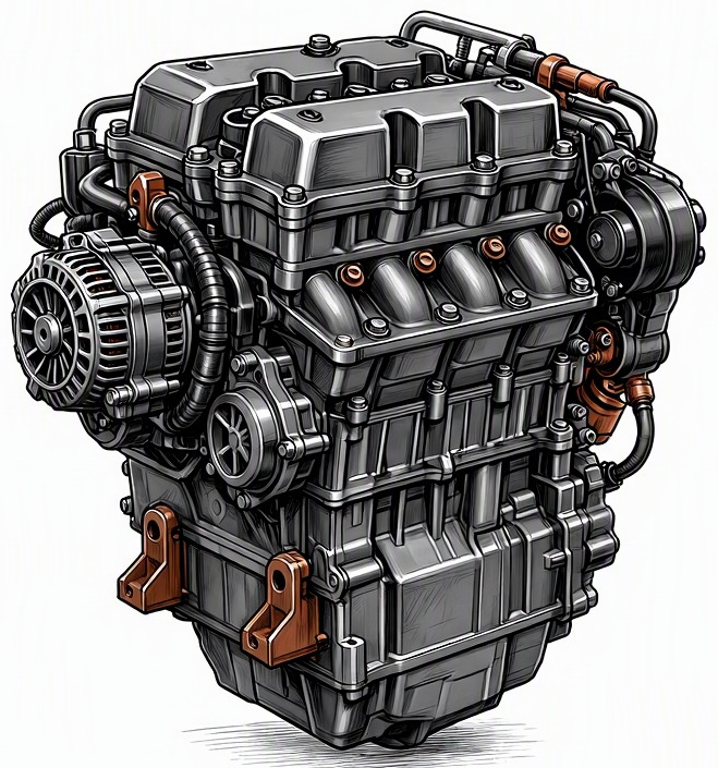
Problem Overview & Engine Systems
The integrity of the engine wiring harness is paramount for the reliable operation of any modern internal combustion engine. The malfunction characterized as “Engine wiring harness connector locking tab breakage” refers to the mechanical failure of the retention mechanism on a plastic or composite electrical connector housing. These locking tabs, often designed as a flexible snap-fit or lever-actuated latch, ensure a secure and stable connection between a sensor, actuator, or control module and the engine’s primary electrical loom. When these tabs fracture or deform beyond their intended design limits, the connector loses its primary means of mechanical retention. This compromise leads to an insecure connection, allowing for micro-movements, vibration-induced dislodgement, or environmental ingress. While the wiring harness itself is an integral part of the vehicle’s electrical system, its connectors directly interface with virtually every engine system requiring electrical input or output. This includes, but is not limited to, sensors for the fuel delivery system (e.g., fuel injector connectors, fuel pressure sensors), ignition system (e.g., ignition coil connectors, crankshaft/camshaft position sensors), valvetrain control (e.g., VVT/VVT-i solenoid connectors), exhaust gas management (e.g., O2 sensors, exhaust gas recirculation valve), forced induction systems (e.g., turbocharger wastegate actuator, boost pressure sensor), and the various sensors critical for engine management by the Powertrain Control Module (PCM) or Engine Control Unit (ECU), such as Manifold Absolute Pressure (MAP) sensors, Engine Coolant Temperature (ECT) sensors, and throttle body position sensors. The direct internal components affected are the electrical terminals within the connector housing, which, without proper retention, can lose contact, leading to intermittent or complete signal loss or impedance fluctuations.
Common Symptoms
- Primary Signs: A prominent illumination of the Check Engine Light (CEL) or Malfunction Indicator Lamp (MIL) is almost guaranteed, often accompanied by specific Diagnostic Trouble Codes (DTCs) pointing to circuit malfunctions or irrational sensor readings. Depending on the affected circuit, other dashboard warning lights might activate, such as Traction Control (TCS) or Anti-lock Braking System (ABS) if related speed sensors or wheel speed sensors (part of the extended vehicle electrical system) are involved. There are typically no direct unique noises or exhaust smoke colors specifically linked to a broken locking tab, but rather symptoms generated by the subsequent electrical fault.
- Engine Behavior Changes: The engine’s operational characteristics will deteriorate significantly, varying based on the criticality of the affected circuit. Common manifestations include engine misfires (if an ignition coil or fuel injector connector is compromised), severe power loss and reduced acceleration, fluctuating idle speed or rough idling, and engine stalling. The vehicle may exhibit a rough running condition, difficulty starting, or complete failure to start. Intermittent faults can lead to sudden, unpredictable changes in engine performance, such as momentary hesitations or surges, making the vehicle unreliable and potentially unsafe to operate. Transmission shifting irregularities can also occur if signals from engine sensors critical for transmission control (e.g., throttle position, engine speed) are affected.
Root Causes & Failure Mechanisms
- Mechanical Stress and Fatigue: Repeated vibrations from engine operation, improper handling during maintenance procedures, or accidental snagging of the harness during service can induce mechanical stress on the plastic locking tabs. Over time, this stress leads to material fatigue, embrittlement, and eventual fracture.
- Thermal Degradation and Cycling: The engine bay experiences significant temperature fluctuations. Prolonged exposure to high under-hood temperatures (especially near exhaust components) can accelerate the degradation of plastic materials, causing them to become brittle and prone to cracking. Repeated thermal cycling further exacerbates this, inducing expansion and contraction that weakens the tab structure.
- Chemical Exposure: Contamination from engine fluids such as oil, coolant, brake fluid, or harsh cleaning agents can chemically attack the plastic composition of the connector housing. This leads to softening, weakening, or embrittlement of the material, compromising the mechanical integrity of the locking tab.
- Incorrect Disconnection/Connection Procedures: Lack of knowledge or impatience during component replacement often leads technicians or owners to force connectors apart without properly disengaging the locking mechanism. This direct application of excessive force is a primary cause of immediate tab breakage. Similarly, attempting to seat a connector with a misaligned tab can deform or break it.
- Design and Material Limitations: In some instances, the original equipment manufacturer (OEM) design might feature an undersized or improperly reinforced locking tab, or utilize a plastic compound with insufficient heat or chemical resistance for the application. This inherent weakness makes the component susceptible to premature failure under normal operating conditions.
How to Diagnose and Troubleshoot
Diagnosing a broken wiring harness connector locking tab requires a systematic approach, combining diagnostic tools with meticulous visual inspection and tactile examination.
- OBD-II Scan and DTC Analysis: Begin by connecting an OBD-II scanner to retrieve any stored or pending Diagnostic Trouble Codes (DTCs). Fault codes related to circuit high/low input, intermittent signals, or sensor/actuator performance outside expected parameters (e.g., P0171 – System Too Lean, P030x – Cylinder Misfire, P0113 – IAT Sensor High Input) will help narrow down the affected system and potentially the specific component. Note down all relevant DTCs.
- Visual Inspection of Suspect Connectors: Based on the DTCs, visually inspect the wiring harness connectors associated with the implicated sensors or actuators. Carefully examine the locking tabs for any signs of breakage, cracking, deformation, or complete absence. Check for any signs of corrosion, fraying wires near the connector, or loose terminals. Pay close attention to connectors that are frequently handled during service or are in high-heat/vibration areas.
- Tactile Wiggle Test: With the engine running (if possible and safe), or with the ignition ON, gently wiggle and manipulate the wiring harnesses and individual connectors suspected of having a broken tab. Monitor live data on the OBD-II scanner for sudden changes in sensor readings or actuator commands. Listen for changes in engine idle quality, misfires, or stalling. This test helps identify intermittent connections.
- Connector Retention Check: Physically attempt to pull the suspect connector off its mating component without pressing the release tab. If it detaches easily or wiggles significantly, the locking mechanism is compromised.
- Pin Tension Test (if necessary): If a connector appears visually intact but symptoms persist, a specialized pin tension tool can be used to check the retention force of the individual terminals within the connector housing. Weak pin tension can lead to poor electrical contact even if the outer housing is secure.
- Multimeter/Oscilloscope Diagnostics: For complex or intermittent faults, use a digital multimeter (DMM) or an oscilloscope to perform continuity, voltage drop, and signal integrity tests directly at the affected connector. Back-probe the terminals while the connector is seated to verify proper signal transmission. Look for erratic voltage readings or distorted waveforms indicating an unstable connection.
Recommended Repairs and Solutions
The repair strategy for a broken engine wiring harness connector locking tab typically involves replacing the compromised connector housing rather than attempting to repair the tab itself, as plastic repair often lacks the necessary durability for the engine environment. The scale of repair can range from a simple connector swap to a partial or full harness replacement, depending on the extent of damage and wire integrity.
- Connector Housing Replacement: This is the most common and effective solution. The damaged connector housing is carefully removed, and the individual electrical terminals are extracted using specialized terminal removal tools. These terminals are then transferred to a new, identical OEM-quality or equivalent aftermarket connector housing. It is critical to ensure each terminal is seated correctly and securely within the new housing. A small amount of dielectric grease can be applied to the terminals to prevent corrosion and improve electrical contact.
- Wire Repair/Repinning: If the wires leading into the connector have been chafed, pulled, or otherwise damaged due to the loose connector, they must be repaired. This involves carefully splicing in new wire sections using appropriate crimp connectors (e.g., heat-shrinkable butt connectors) or soldering, followed by insulation. If terminals themselves are damaged, they must be replaced by crimping new terminals onto the existing wire.
- Sectional Harness Replacement: In cases where multiple connectors on a specific sub-harness are damaged, or the wiring itself has sustained extensive damage beyond individual wire repair, it may be more efficient and reliable to replace a section of the wiring harness. This typically involves identifying the specific sub-harness (e.g., injector harness, sensor harness), disconnecting it from the main loom or ECU, and installing a new section.
- Full Wiring Harness Replacement: For severe, widespread damage across numerous connectors and wiring, or when a critical main harness is compromised, a complete engine wiring harness replacement might be necessary. This is a labor-intensive and costly repair but ensures the integrity of the entire electrical system.
Driving Safety Risk Factors: A broken connector locking tab poses significant driving safety risks. An intermittent or complete loss of crucial sensor data (e.g., camshaft/crankshaft position, throttle position) or actuator control (e.g., fuel injectors, ignition coils) can lead to sudden engine stalling at high speeds, unpredictable power loss, or uncontrolled acceleration. This loss of control can lead to collisions. Furthermore, impaired engine performance due to sensor malfunctions can lead to excessive emissions, potentially failing emissions inspections. It is strongly advised not to operate a vehicle with known critical wiring harness connector issues.
Maintenance Recommendations
Preventing engine wiring harness connector locking tab breakage primarily revolves around proper handling during service, meticulous inspection, and protection from environmental factors.
- Adhere to Proper Disconnection Procedures: Always use the correct technique and tools when disconnecting electrical connectors. Understand the specific locking mechanism (e.g., push tab, pull tab, slide lock, lever release) for each connector. Never pull directly on the wires, only on the connector body. Apply gentle, steady pressure, and ensure the release tab is fully disengaged.
- Regular Visual Inspections: During routine maintenance (e.g., oil changes, filter replacements), visually inspect accessible wiring harnesses and connectors for signs of damage. Look for cracked or missing locking tabs, loose connections, chafed wires, or signs of rodent damage. Pay particular attention to connectors in high-heat or high-vibration zones.
- Protect from Environmental Exposure: Ensure that all wiring harnesses are properly routed and secured away from direct contact with hot engine components (exhaust manifolds, turbocharger housings) and moving parts (belts, pulleys). Address any fluid leaks (oil, coolant, brake fluid) promptly to prevent chemical degradation of plastic components.
- Use OEM or Quality Aftermarket Components: When replacing sensors, actuators, or sections of the harness, opt for OEM or high-quality aftermarket parts that ensure proper fitment and material durability. Inferior aftermarket connectors may use brittle plastics prone to premature failure.
- Avoid Over-Torquing and Improper Tool Use: When working near wiring harnesses, use appropriate hand tools and avoid excessive force that could inadvertently damage connectors or wires. Ensure wiring is secured back in its original clamps and routing after any repair or inspection to prevent chafing and vibration damage.
