
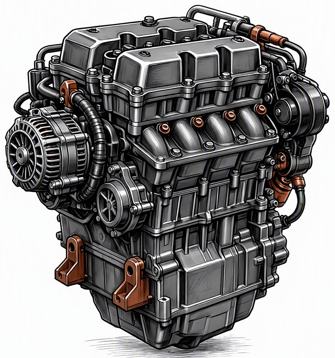
Problem Overview & Engine Systems
The “Coolant temperature sensor incorrect reading” malfunction refers to a scenario where the Engine Control Module (ECM) or Powertrain Control Module (PCM) receives an erroneous signal from the Coolant Temperature Sensor (CTS), misrepresenting the actual temperature of the engine’s coolant. This discrepancy can range from a minor inaccuracy to a complete failure, resulting in readings that are consistently too high, too low, or erratically fluctuating. The CTS is an integral component of the Cooling System and the overarching Engine Management System. It typically consists of a thermistor (a type of resistor whose resistance varies significantly with temperature) submerged in the engine coolant, usually located in the cylinder head or intake manifold. The ECM supplies a reference voltage (typically 5V) to the sensor, and the thermistor’s changing resistance alters this voltage, which the ECM then interprets as a temperature. Internal components directly affected by an incorrect CTS reading include the ECM/PCM itself, which relies on this data for critical calculations. These calculations influence fuel injection timing and pulse width, ignition timing, idle air control valve operation, variable valve timing actuation, cooling fan engagement, emissions control systems, and even transmission shift strategies in some vehicles. A false low reading can lead to the ECM enriching the fuel mixture and retarding timing, similar to a cold-start strategy, while a false high reading can lean out the mixture and advance timing excessively, or trigger premature cooling fan operation.
Common Symptoms
- Primary Signs: Check Engine Light (CEL) illumination with stored Diagnostic Trouble Codes (DTCs) such as P0115 (Engine Coolant Temperature Circuit Malfunction), P0117 (Engine Coolant Temperature Circuit Low Input), P0118 (Engine Coolant Temperature Circuit High Input), or P0116 (Engine Coolant Temperature Circuit Range/Performance Problem). The engine’s temperature gauge on the dashboard may display erratic readings, or remain consistently low/high regardless of actual engine temperature. There might be an noticeable increase in exhaust emissions, potentially indicated by a strong fuel smell from the exhaust pipe due to an excessively rich mixture.
- Engine Behavior Changes: The vehicle may exhibit poor fuel economy due to an overly rich fuel mixture. Rough idling, hesitation upon acceleration, or a general lack of power can occur. Extended cranking time, especially during cold starts, is common if the ECM believes the engine is warmer than it actually is, leading to an insufficient fuel enrichment strategy. Conversely, if the ECM thinks the engine is perpetually cold, the engine may run excessively rich, leading to carbon build-up, oxygen sensor contamination, and potential catalytic converter damage. In severe cases, particularly with a false low reading, the engine may experience actual overheating because the cooling fans are not activated or the thermostat is not signaled to open correctly, leading to potential engine damage or failure to start at all.
Root Causes & Failure Mechanisms
- Sensor Degradation and Internal Failure: Over time, the thermistor element within the CTS can degrade due to thermal cycling, vibration, or exposure to contaminated coolant. This leads to a shift in its resistance-to-temperature curve, causing it to send inaccurate voltage signals to the ECM. Internal corrosion or fracturing of the sensor’s leads can also cause intermittent or complete failure.
- Electrical Circuit Malfunctions: This category encompasses issues with the wiring harness connecting the CTS to the ECM. Common problems include chafing of wires against engine components, leading to a short to ground or an open circuit. Corrosion at the sensor connector pins or ECM connector pins can increase circuit resistance or cause intermittent contact, resulting in erroneous signal voltage. Rodent damage to the wiring is also a frequent cause of electrical circuit issues.
- Coolant Level and Air Pockets: If the engine coolant level is critically low, or if air pockets are present around the CTS, the sensor may not be fully submerged in liquid coolant. Consequently, it will read the temperature of air or steam, which can be significantly different from the actual coolant temperature, leading to an incorrect reading even if the sensor itself is functioning correctly.
- Thermostat Malfunction (Indirect Cause): While not a direct sensor failure, a thermostat that is stuck open or closed can lead to the coolant temperature stabilizing at an abnormal level (too cold or too hot). The CTS will accurately report this abnormal temperature, which might then be misinterpreted as an “incorrect reading” if the actual engine operating temperature is expected to be different. The ECM might flag a performance code (P0116) if the temperature change rate or target temperature is not met within expected parameters.
- ECM/PCM Input Circuit Failure: Although less common, an internal fault within the ECM/PCM’s input circuit responsible for processing the CTS signal can lead to incorrect interpretation, despite the sensor and wiring being perfectly functional. This typically requires specialized diagnostic tools and expertise to pinpoint.
How to Diagnose and Troubleshoot
Diagnosing an incorrect coolant temperature sensor reading requires a systematic approach, combining diagnostic scan tools with manual electrical and thermal checks:
- OBD2 Scan and Live Data Analysis: Connect an OBD2 scanner. Retrieve any stored DTCs; P0115, P0116, P0117, P0118 are primary indicators. Access live data and monitor the “Engine Coolant Temperature (ECT)” parameter. With a cold engine (after an overnight soak), compare the ECT reading to the “Intake Air Temperature (IAT)” reading and ambient temperature. They should be very close. Start the engine and observe the ECT parameter as the engine warms up; it should rise steadily and smoothly. Anomalies include readings that are stuck at a maximum (e.g., -40°C or 150°C), erratic fluctuations, or a failure to rise at all.
- Visual Inspection: Disconnect the battery. Visually inspect the CTS and its connector for signs of damage, corrosion, or coolant leaks. Follow the wiring harness from the CTS to the ECM, checking for chafing, cuts, or rodent damage. Ensure the coolant reservoir is at the correct level and that no significant air pockets are audible in the cooling system.
- Multimeter Electrical Tests:
- Reference Voltage: With the ignition ON and the CTS disconnected, use a multimeter to measure the voltage between the 5V reference pin and the ground pin at the harness connector. It should be approximately 5V.
- Ground Integrity: Measure resistance between the ground pin at the harness connector and chassis ground. It should show very low resistance (near 0 ohms).
- Sensor Resistance Check: Disconnect the CTS. Remove it from the engine if possible. Place the sensor in a beaker of water with a known thermometer. Using the multimeter set to ohms, measure the resistance across the sensor terminals. Heat the water slowly and record resistance at various temperatures (e.g., 0°C, 20°C, 50°C, 90°C). Compare these readings against the vehicle manufacturer’s specifications (found in service manuals); resistance should decrease as temperature increases.
- Wiring Continuity: Disconnect both the CTS and the ECM connectors. Use the multimeter to check for continuity in both signal and reference wires from the CTS connector to the ECM connector. Check for shorts to ground or shorts to power in the wires.
- Infrared Thermometer Verification: Use an infrared thermometer to measure the actual temperature of the thermostat housing or the area around the CTS. Compare this physical temperature reading to the live data ECT reading from the OBD2 scanner. A significant discrepancy (e.g., 20°C or more) indicates an issue with the sensor, its circuit, or the ECM’s interpretation.
Recommended Repairs and Solutions
The primary repair for an incorrect coolant temperature sensor reading typically involves component replacement. Most commonly, the Coolant Temperature Sensor (CTS) itself requires replacement. This is a relatively straightforward repair on most engines, often requiring draining a small amount of coolant before removal and replacement. If electrical tests indicate a fault in the wiring harness, targeted wiring repair or replacement of the affected harness section is necessary. Corroded or damaged connectors should be replaced with new pigtail connectors. If low coolant levels or air pockets were identified, a complete coolant system flush and refill with proper bleeding procedures is essential. In cases where a thermostat malfunction is indirectly causing the incorrect temperature reading, the thermostat should be replaced. An ECM/PCM fault is the least common cause, but if all other possibilities are exhausted, the ECM/PCM may require reprogramming or replacement, which is a significantly more complex and costly repair. Driving safety risks associated with this malfunction include the potential for severe engine overheating and subsequent catastrophic damage (e.g., head gasket failure, warped cylinder head, engine seizure) if the cooling fans are not activated or the engine continues to run at excessively high temperatures. Conversely, chronic over-enrichment due to a false cold reading can lead to catalytic converter damage and significantly increased emissions.
Maintenance Recommendations
Preventing an incorrect coolant temperature sensor reading primarily revolves around diligent maintenance of the cooling system and electrical integrity:
- Adhere to Coolant Service Intervals: Follow the manufacturer’s recommended coolant type and change intervals. Old or contaminated coolant can lead to corrosion within the cooling system, potentially damaging the CTS or causing sludge buildup that insulates the sensor from the actual coolant temperature. Ensure the coolant level is always maintained between the minimum and maximum marks in the reservoir.
- Regular Visual Inspections: Periodically inspect the engine compartment for any signs of wiring damage, especially around sensors. Check for chafing, cuts, or loose connectors. During routine maintenance, observe the CTS and its wiring for any visual signs of wear or degradation.
- Thermostat Health: While not a direct maintenance item for the sensor, ensuring the thermostat is functioning correctly (opening and closing at specified temperatures) helps the overall cooling system operate within its design parameters, reducing stress on the CTS and ensuring it always reads true operational temperatures. Consider replacing the thermostat as a preventative measure during major cooling system overhauls (e.g., water pump replacement).
- Sensor Lifespan Consideration: Although not typically a scheduled replacement item, on high-mileage vehicles (e.g., over 150,000 miles or 250,000 km), proactively replacing the CTS can prevent future issues, as thermistors can degrade over extended periods of thermal cycling.
- Professional Diagnostic Checks: If experiencing any of the symptoms mentioned, prompt professional diagnostic intervention can prevent minor sensor inaccuracies from escalating into more significant engine problems. Monitoring live data during routine service can also help identify incipient sensor degradation before a fault code is triggered.
