
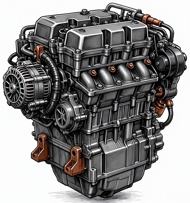
Problem Overview & Engine Systems
Ignition module overheating represents a critical thermal failure within the engine’s ignition system, directly compromising spark generation and engine operational stability. The ignition module, often referred to as an igniter, power output stage, or sometimes integrated within the ignition coil assembly (e.g., coil-on-plug modules), is an electronic device responsible for switching the primary current to the ignition coil at precise timings dictated by the Engine Control Unit (ECU). This rapid switching induces the high voltage necessary for spark plug firing. Overheating occurs when the module’s internal semiconductor components (typically power transistors or IGBTs – Insulated Gate Bipolar Transistors) exceed their designed thermal operating limits, leading to performance degradation, intermittent failure, or complete breakdown.
This malfunction primarily belongs to the Electrical System and specifically the Ignition System. While not a direct component of the Cylinder Block, Valvetrain, or Lubrication system, its failure directly impacts combustion events within the cylinders. Internal components directly affected include the module’s power switching transistors, control circuitry, and potentially the primary windings of associated ignition coils if the module is integrated or if its failure induces excessive current draw. Prolonged overheating can lead to physical damage such as cracking of the potting compound, visible discoloration, or even melting of the plastic housing, indicating irreversible component degradation.
Common Symptoms
- Primary Signs:
- Illumination of the Check Engine Light (CEL), often accompanied by Diagnostic Trouble Codes (DTCs) related to misfires (e.g., P030x for specific cylinder misfires, P0300 for random/multiple misfires) or ignition circuit malfunctions (e.g., P035x for ignition coil primary/secondary circuit).
- Occasional engine stalling, especially after prolonged operation or under heavy load.
- Difficulty restarting the engine when it is hot, but potentially starts normally after a cool-down period.
- Engine Behavior Changes:
- Intermittent misfires: Often noticeable as a skip, stumble, or hesitation, particularly under acceleration, heavy load, or at operating temperature.
- Significant power loss: Due to incomplete combustion in one or more cylinders.
- Rough or fluctuating idle speed: The engine may shake or vibrate excessively at idle.
- Reduced fuel economy: Inefficient combustion leads to higher fuel consumption.
- Engine sputtering or surging: Irregular power delivery, feeling like the engine is “choking” or momentarily losing power.
Root Causes & Failure Mechanisms
- Inadequate Heat Dissipation: The most prevalent cause. This can stem from improper mounting of the module to its heat sink (e.g., corroded or improperly applied thermal paste/compound), a loose mounting, or a compromised heat sink design. The inability to transfer heat effectively away from the power transistors causes localized thermal runaway.
- Excessive Current Draw from Ignition Coils: Faulty ignition coils (either internal shorts in primary or secondary windings, or degraded insulation) can demand higher than specified primary current from the ignition module. This overcurrent directly stresses the module’s power transistors, generating excessive internal heat.
- High Under-Hood Ambient Temperatures: Malfunctions in the engine cooling system (e.g., failing radiator fans, clogged radiator fins, low coolant levels leading to engine overheating) can significantly raise the ambient temperature in the engine bay, exceeding the design limits of the ignition module. Prolonged idling in hot climates exacerbates this.
- Internal Component Degradation/Design Flaws: Over time, repeated thermal cycling and electrical stress can degrade the internal semiconductor junctions of the power transistors within the module. Some modules may also have inherent design or manufacturing flaws that make them more susceptible to thermal failure under normal operating conditions.
- Voltage Regulation Issues: An alternator overcharging or persistent voltage spikes in the electrical system can subject the ignition module to voltages beyond its design limits, leading to increased power dissipation and heat generation.
- Environmental Factors: Exposure to excessive vibration, moisture ingress, or corrosive elements can lead to internal shorts or degradation of the module’s protective potting compound, compromising thermal management and electrical integrity.
How to Diagnose and Troubleshoot
Accurate diagnosis of ignition module overheating requires a methodical approach utilizing specialized tools:
- OBD2 Scanner & Live Data Analysis:
- Connect an OBD2 scanner to retrieve all stored, pending, and history DTCs. Prioritize codes related to misfires (P0300-P0306), ignition primary/secondary circuits (P0350-P0356), or ignition module specific codes.
- Monitor live data parameters, specifically misfire counters for individual cylinders. Note if misfires occur predominantly on one or more cylinders and if they increase under load or when the engine is fully warmed up.
- Observe ignition timing, engine coolant temperature (ECT), intake air temperature (IAT), and vehicle speed.
- Visual Inspection:
- Carefully inspect the ignition module and its associated wiring harness. Look for signs of heat damage on the module’s housing (discoloration, blistering, melting), frayed or burnt wiring, corroded connectors, or loose connections.
- Verify proper mounting of the module to its heat sink or chassis. Ensure there is no debris obstructing airflow around the module.
- Multimeter Testing:
- With the ignition OFF and key removed, test the resistance of the ignition coil primary windings (if accessible and separate from the module) against manufacturer specifications. A coil with too low resistance can draw excessive current.
- Check for proper voltage supply (B+) and ground integrity at the module connector with the ignition ON. Verify the control signal from the ECU (often a varying voltage or pulse width modulated signal, depending on the system).
- Check continuity and resistance of the wiring harness leading to the module and coils.
- Oscilloscope Waveform Analysis:
- This is arguably the most definitive diagnostic tool. Connect an oscilloscope to the primary side of the ignition coil circuit (or the module’s output to the coil).
- Analyze the primary ignition waveform: Look for irregular coil saturation time (dwell time), excessive current draw (indicated by the current ramp), or signs of voltage spikes that could indicate an internal coil short or module failure. An ignition module failing due to overheating may exhibit erratic or missing primary coil switching events as it approaches critical temperature.
- Observe secondary ignition waveforms (via a coil-on-plug probe or inductive pickup) to identify misfires under various engine conditions (idle, snap throttle, load).
- Thermal Inspection:
- Use an infrared thermometer or a thermal imaging camera to measure the surface temperature of the ignition module and surrounding components when the engine is exhibiting symptoms. Compare the module’s temperature to that of adjacent components and to manufacturer specifications for operational temperature range. A significantly higher temperature on the module indicates poor heat dissipation or excessive internal heat generation.
- Stress Testing:
- If the fault is intermittent and temperature-dependent, operate the engine under conditions that typically trigger the symptoms (e.g., prolonged idle, specific RPM range, hot restart) while continuously monitoring live data and module temperature.
Recommended Repairs and Solutions
Addressing ignition module overheating typically involves component replacement and rectification of the underlying cause:
- Ignition Module Replacement: The primary repair is to replace the faulty ignition module. It is crucial to use an Original Equipment Manufacturer (OEM) or a high-quality aftermarket part that meets or exceeds OEM specifications. Inferior parts may have inadequate thermal management or lower-quality internal components, leading to a recurrence of the issue.
- Ensure Proper Heat Dissipation:
- Before installing the new module, thoroughly clean the mating surfaces of the module and its heat sink (or engine chassis if directly mounted) to ensure excellent thermal contact.
- Apply a new layer of high-quality thermal conductive paste or compound (similar to that used for computer CPUs) if specified by the manufacturer.
- Tighten mounting bolts to the manufacturer’s specified torque to ensure optimal thermal transfer without distorting the module.
- Address Root Causes:
- Replace Faulty Ignition Coils: If diagnostics (oscilloscope, multimeter) indicate excessive current draw or internal shorts in the ignition coils, they must be replaced, even if they are currently functional. Failed coils are a common precursor to module failure.
- Repair Wiring & Connectors: Replace any damaged, corroded, or loose wiring and connectors leading to the ignition module or coils. Ensure proper crimping and sealing.
- Rectify Cooling System Issues: If high under-hood temperatures are a contributing factor, diagnose and repair any issues with the engine cooling system, such as faulty radiator fans, a clogged radiator, or low coolant levels.
- Inspect Charging System: If voltage regulation issues are suspected, diagnose and repair the alternator or voltage regulator to ensure stable and correct system voltage.
The repair scale for ignition module overheating is typically limited to component replacement (module, coils, wiring). A complete engine overhaul is not required unless secondary damage, such as catalytic converter degradation from prolonged misfires, has occurred. Driving with an overheating ignition module poses significant safety risks due to potential sudden engine stalling or severe power loss, especially at highway speeds. It also leads to increased emissions and potential damage to other engine components.
Maintenance Recommendations
Preventing ignition module overheating relies on proactive maintenance and judicious component choices:
- Adhere to Manufacturer’s Service Intervals: Promptly replace spark plugs and, if specified, ignition coils according to the vehicle manufacturer’s recommended intervals. Worn spark plugs or aging coils can increase the electrical load on the ignition module, leading to premature failure.
- Use OEM or High-Quality Aftermarket Components: When replacing ignition components (spark plugs, coils, modules), always opt for OEM parts or reputable aftermarket brands that meet or exceed original equipment specifications. Cheaper, inferior parts often have lower thermal tolerances and can fail prematurely.
- Regular Electrical System Checks: During routine service, inspect visible wiring harnesses for signs of chafing, cracking, or corrosion, especially in high-heat areas around the engine. Ensure all electrical connectors are clean and securely seated.
- Maintain Engine Cooling System: Ensure the engine’s cooling system (radiator, cooling fans, coolant levels, thermostat) is in optimal working condition. A properly functioning cooling system prevents excessive under-hood temperatures that can stress electronic components.
- Address Misfires Promptly: Do not ignore recurring misfires or symptoms of poor engine performance. Early diagnosis and repair of misfire causes can prevent cascading failures involving the ignition module or catalytic converter.
- Professional Installation: When replacing ignition modules or coils, ensure they are installed by a qualified technician who understands the importance of proper heat sink preparation and mounting torque.
- Operational Habits: While less direct, minimizing prolonged idling in extreme hot weather conditions can reduce cumulative thermal stress on under-hood electronics.
