
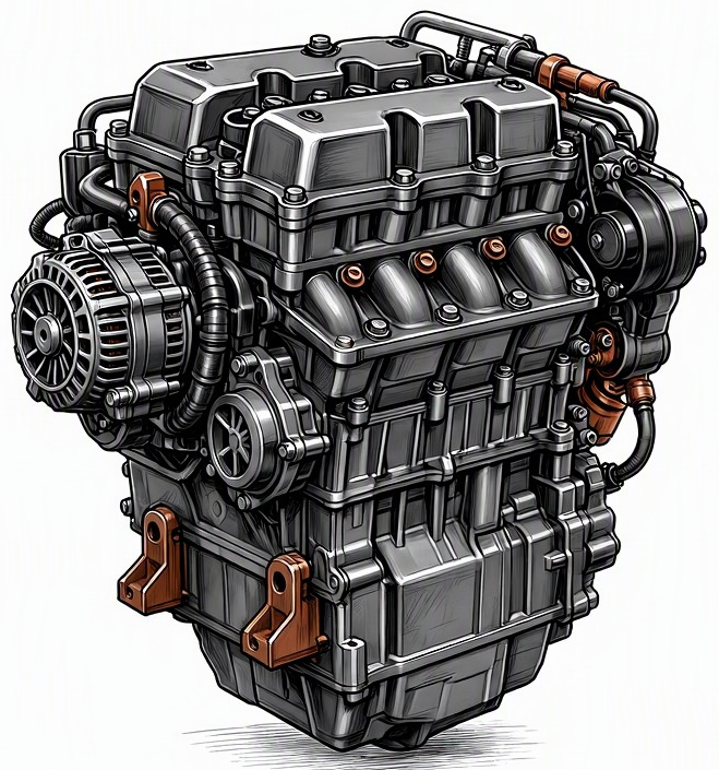
Problem Overview & Engine Systems
Throttle Position Sensor (TPS) dead spots represent a specific electrical malfunction within the potentiometric sensor responsible for relaying throttle plate angle to the Powertrain Control Module (PCM) or Engine Control Unit (ECU). The TPS is a variable resistor, typically featuring a resistive track and a wiper arm. A “dead spot” occurs when the conductive material of the resistive track wears away or becomes contaminated in specific, frequently used areas (e.g., idle, light cruise, or specific acceleration points). This wear or contamination results in an open circuit or excessively high resistance at that particular throttle plate angle, causing a momentary loss or erratic transmission of the throttle position signal. The PCM, relying on this critical input for fuel injection pulse width, ignition timing, and transmission shift strategies, receives incorrect or no data, leading to significant engine performance issues.
The TPS is an integral component of the Engine Management System (EMS). In cable-actuated throttle bodies, it is directly mounted to the throttle shaft. In modern drive-by-wire (Electronic Throttle Control – ETC) systems, the TPS is often integrated into the electronic throttle body assembly, working in conjunction with an Accelerator Pedal Position (APP) sensor and a throttle motor to manage throttle plate movement. This malfunction directly impacts the Fuel System (incorrect fuel trim, lean/rich conditions), the Ignition System (improper timing advance), the Transmission Control System (erratic shift points), and Emission Control Systems. Internal components directly affected are the resistive track and the wiper arm within the TPS unit itself. Indirectly, prolonged incorrect data can lead to issues with spark plugs (fouling), catalytic converter (overheating due to rich conditions), and potentially transmission wear due to improper shift engagement.
Common Symptoms
- Primary Signs: The Check Engine Light (CEL) will almost certainly illuminate, accompanied by Diagnostic Trouble Codes (DTCs) such as P0120-P0124 (TPS ‘A’ Circuit Malfunction), P0220-P0224 (TPS ‘B’ Circuit Malfunction, if dual sensors), or P2135 (Throttle/Pedal Position Sensor/Switch ‘A’/’B’ Voltage Correlation). No specific noises or exhaust smoke are typically direct symptoms, although poor combustion can eventually lead to black smoke (rich) or engine knocking if severe enough.
- Engine Behavior Changes:
- Hesitation or Stumble: Noticeable lag, bogging, or stumble during acceleration, particularly at specific throttle openings where the dead spot occurs.
- Intermittent Power Loss: The engine may momentarily lose power or feel sluggish, especially when modulating the throttle.
- Fluctuating or Rough Idle: The engine idle speed may become erratic, surging, or drop below specifications, especially when returning to idle or during slight throttle applications.
- Surging or Bucking: The vehicle may surge or buck intermittently at steady cruise speeds due to the PCM receiving incorrect throttle input.
- Transmission Shifting Issues: Automatic transmissions may exhibit harsh shifts, delayed shifts, or “hunting” for gears, as the transmission control module relies on TPS data for load calculation.
- Engine Stall: The engine may occasionally stall, particularly during deceleration or when the throttle is quickly released, as the PCM struggles to maintain idle speed with corrupt data.
- Reduced Fuel Economy: Inaccurate fuel trim due to incorrect throttle input can lead to increased fuel consumption.
- Limp Home Mode: In severe cases, especially with drive-by-wire systems, the PCM may activate a “limp home” or “reduced power” mode to prevent engine damage or uncontrolled acceleration.
Root Causes & Failure Mechanisms
- Friction Wear of Resistive Track: This is the predominant cause. The wiper arm, which slides along the resistive track within the TPS, experiences mechanical friction during throttle actuation cycles. Over time and extensive use, this friction wears down the conductive material of the track, especially at frequently utilized throttle angles (e.g., idle position, common highway cruise positions). This wear creates areas of increased resistance or complete electrical discontinuity, manifesting as “dead spots.”
- Contamination and Corrosion: Ingress of moisture, dirt, dust, oil vapor, or other environmental contaminants into the sealed TPS unit can deposit on the resistive track or wiper contacts. These deposits can create insulating barriers or promote corrosion, leading to intermittent or complete loss of electrical contact at specific points during throttle movement.
- Thermal Degradation and Vibration Fatigue: Prolonged exposure to high engine bay temperatures can degrade the internal materials of the TPS, including the resistive element, wire bonding, or solder joints. Constant engine vibrations can also contribute to the physical wear of the wiper arm against the track or cause micro-fractures in internal electrical connections, leading to intermittent failures.
- Manufacturing Defects: Although less common with established brands, inherent flaws in the manufacturing process, such as inconsistent resistive material application, poor quality wiper contacts, or inadequate sealing, can lead to premature failure and dead spots.
How to Diagnose and Troubleshoot
Diagnosing TPS dead spots requires precise electrical measurement and analysis of the sensor’s output:
- OBD2 Scanner – Live Data Analysis:
- Connect an OBD2 diagnostic scanner to the vehicle’s Data Link Connector (DLC).
- Access the live data stream and monitor the “Throttle Position Sensor Voltage” (or percentage). Many vehicles have two TPS sensors (TPS1 and TPS2 or A and B) for redundancy in drive-by-wire systems; monitor both.
- With the ignition ON, engine OFF (KOEO), slowly and steadily depress the accelerator pedal from fully closed (idle) to wide-open throttle (WOT), then slowly release it. Repeat this process several times.
- Observe the voltage (or percentage) readings. For a typical TPS, the voltage should sweep smoothly and linearly from approximately 0.5V (closed throttle) to 4.5V-5.0V (WOT). A dead spot will appear as a sudden drop, spike, plateau, or momentary loss of signal (e.g., jumping from 2.0V to 0V then back to 2.1V, or momentarily flatlining at a specific voltage).
- Note any DTCs related to TPS circuit range/performance or correlation errors between dual TPS sensors.
- Digital Multimeter (DMM) – Voltage Sweep Test:
- Locate the TPS on the throttle body. Identify the sensor’s three wires: 5V reference, signal return (ground), and signal output. Consult the vehicle’s wiring diagram for pin assignments.
- Back-probe the signal output wire of the TPS with the positive lead of the DMM set to DC voltage. Connect the negative lead to a known good chassis ground.
- With the ignition ON, engine OFF (KOEO), slowly actuate the throttle plate by hand (or have an assistant slowly depress the accelerator pedal if drive-by-wire).
- Observe the DMM display. The voltage should increment smoothly and linearly without any sudden drops, erratic jumps, or flat spots as the throttle plate moves through its full range. Any discontinuity indicates a dead spot.
- Oscilloscope – Waveform Analysis (Most Definitive):
- Connect the oscilloscope probe to the TPS signal output wire. Connect the ground lead to a reliable chassis ground.
- Set the oscilloscope to a suitable voltage range and time base (e.g., 500mV/Div, 200ms/Div).
- With the ignition ON, engine OFF (KOEO), slowly actuate the throttle from closed to WOT and back to closed, similar to the DMM test.
- A healthy TPS will produce a clean, linear ramp waveform. A dead spot will manifest as a noticeable “glitch” in the waveform – an abrupt vertical line, a momentary flatline, or significant noise/spikes at the point of failure. The oscilloscope’s rapid sampling rate makes it superior for detecting intermittent or very brief dead spots that a DMM might miss.
- Visual Inspection:
- Inspect the TPS connector and wiring harness for signs of physical damage, corrosion, chafing, or loose connections.
- Ensure the TPS is securely mounted to the throttle body.
Recommended Repairs and Solutions
The primary and almost universally effective solution for a Throttle Position Sensor with dead spots is component replacement. TPS units are typically sealed and not designed for internal repair.
- Throttle Position Sensor Replacement:
- Procedure: Disconnect the battery, unplug the electrical connector from the TPS, unbolt the TPS from the throttle body (usually 2-3 screws), install the new TPS, reconnect the electrical connector, and re-connect the battery.
- Calibration/Relearn: After replacement, many vehicles, especially those with drive-by-wire systems, require a TPS relearn or calibration procedure. This may involve specific steps outlined by the manufacturer (e.g., turning the ignition on and off, cycling the pedal) or require a diagnostic scan tool to perform a “Throttle Body Alignment” (TBA) or “TPS Relearn” function. Failure to perform this can result in persistent driveability issues or DTCs.
- Component Replacement Scale: This is a component-level replacement, typically straightforward for a trained technician.
- Throttle Body Replacement (if integrated TPS):
- In many modern drive-by-wire vehicles, the TPS is not a separate replaceable unit but is integrated directly into the electronic throttle body assembly. In these cases, the entire throttle body must be replaced to resolve the TPS dead spot issue. This increases the cost and complexity compared to a standalone TPS replacement.
- Wiring Harness/Connector Repair:
- If diagnostics pinpoint the issue to damaged wiring or a corroded connector leading to the TPS, the harness section or connector pins should be professionally repaired or replaced using OEM-grade terminals and connectors to ensure reliable electrical contact.
Driving Safety Risk Factors: A malfunctioning TPS with dead spots poses significant safety risks. Unpredictable engine behavior, such as sudden hesitation, unexpected power loss during acceleration, or engine stalling, can lead to dangerous situations, especially in heavy traffic, during merging onto highways, or while performing passing maneuvers. The vehicle’s inability to respond predictably to throttle inputs increases the risk of accidents. It is critical to address TPS dead spots immediately upon diagnosis.
Maintenance Recommendations
The Throttle Position Sensor is generally considered a non-serviceable component with no specific scheduled maintenance. However, certain preventative measures and good operational habits can contribute to its longevity:
- Throttle Body Cleanliness: While not directly servicing the TPS, ensuring the throttle body is clean can prevent carbon or oil varnish buildup around the throttle plate. This prevents the throttle plate from sticking or binding, which could put undue mechanical stress on the TPS linkage or integrated components, potentially accelerating wear on the sensor’s internal resistive track. Use appropriate throttle body cleaner specifically designed for modern electronic throttle bodies, avoiding carburetor cleaner on vehicles with special coatings.
- Wiring Harness Integrity: Periodically inspect engine bay wiring harnesses, particularly those connecting to critical sensors like the TPS. Look for signs of chafing, cracking, or damage from heat or rodents. Ensure all electrical connectors are securely seated and free from corrosion. A stable electrical connection is vital for sensor accuracy.
- Avoid Aggressive or Erratic Throttle Habits: While a minor factor, excessively harsh or rapid throttle cycling over the vehicle’s lifespan could theoretically contribute to faster mechanical wear of the TPS’s internal wiper arm and resistive track compared to smooth, controlled throttle inputs.
- Address Engine Vibrations: Ensure engine mounts are in good condition. Excessive engine vibration can lead to premature wear or fatigue of electronic components and their internal connections over extended periods.
- Component Lifespan Awareness: While not a scheduled replacement item, understand that electrical sensors like the TPS have a finite operational lifespan, often exceeding 100,000-150,000 miles. Be vigilant for the described symptoms as the vehicle accumulates high mileage. Replacing the TPS as a preventative measure is generally not recommended unless symptoms begin to manifest or diagnostic tests indicate impending failure.
