
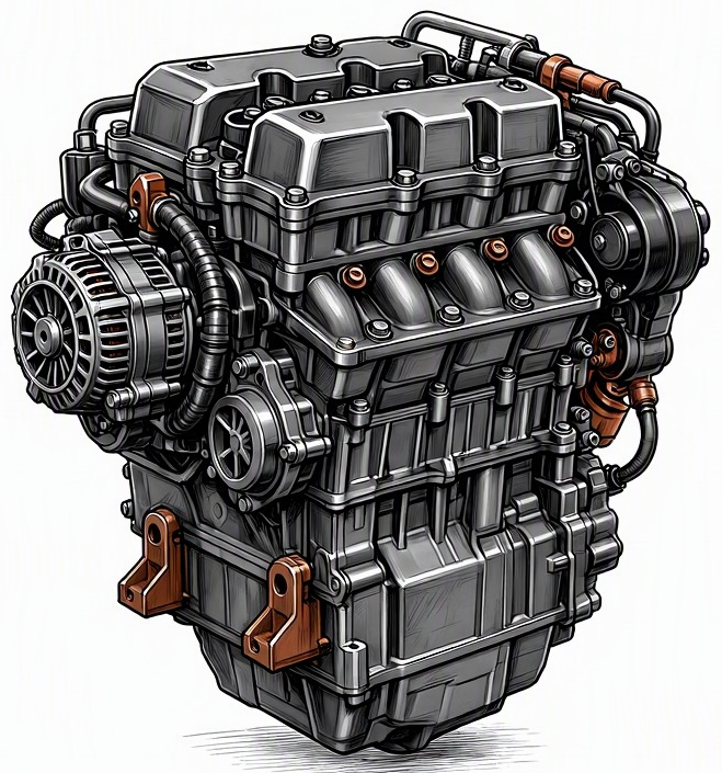
Problem Overview & Engine Systems
The “Accelerator Pedal Position Sensor (APPS) Mismatch” fault refers to a critical discrepancy detected by the Engine Control Module (ECM) or Powertrain Control Module (PCM) between two or more redundant circuits within the accelerator pedal assembly’s position sensor. Modern drive-by-wire (Electronic Throttle Control – ETC) systems utilize the APPS, a non-contacting or potentiometer-based sensor, to convert the mechanical movement of the accelerator pedal into an electrical signal, indicating the driver’s requested engine torque. To ensure system integrity and safety, the APPS typically incorporates multiple independent circuits (often two or three) that output slightly staggered voltage signals (e.g., one circuit 0-5V, another 0-2.5V, or one inversely proportional to the other). These signals are continuously monitored by the ECM/PCM. A “mismatch” condition occurs when the ECM detects that these redundant signals deviate from each other by a predefined threshold for a specific duration, indicating a potential sensor failure or circuit integrity issue. This malfunction directly impacts the Electronic Throttle Control (ETC) system, which is a core component of the engine management system. While not directly affecting the mechanical Cylinder Block, Valvetrain, or Lubrication system, a mismatch fundamentally compromises the ECM’s ability to accurately interpret driver input, leading to severe operational impairments of the Fuel Injection system, Ignition system, and ultimately the engine’s power output. Internally, the directly affected components are the accelerator pedal position sensor unit itself, its associated wiring harness, and the input processing circuits within the Engine Control Module (ECM/PCM).
Common Symptoms
- Primary Signs:
The most prominent primary sign is the illumination of the Check Engine Light (CEL) on the instrument cluster, often accompanied by specific Diagnostic Trouble Codes (DTCs) such as P2120 through P2128 (Accelerator Pedal Position Sensor “A”/”B”/”C” Circuit Malfunction) or P2138 (Accelerator Pedal Position Sensor “D/E/F” Voltage Correlation). Depending on the vehicle manufacturer and fault severity, a Reduced Power Mode or Limp-Home Mode indicator may also illuminate. There are typically no specific noises or exhaust smoke associated with this purely electronic sensor malfunction.
- Engine Behavior Changes:
Engine behavior changes can range from intermittent to severe and include erratic or unresponsive throttle action, where pressing the accelerator pedal produces little to no change in engine RPM or vehicle speed. The engine may enter limp-home mode, severely limiting power and speed (e.g., 20-30 MPH maximum). Other symptoms may include sudden, unintended acceleration or deceleration, intermittent loss of engine power during driving, rough or fluctuating idle speed (as the ECM misinterprets pedal position and attempts to compensate), or even engine stalling, particularly when decelerating or coming to a stop.
Root Causes & Failure Mechanisms
- Internal Sensor Component Degradation:
Wear and tear on the resistive tracks or Hall-effect elements within the APPS module. Over time, continuous pedal actuation can abrade the conductive material in potentiometers, leading to erratic resistance readings. For Hall-effect sensors, magnetic material degradation or internal electronic component fatigue can cause inconsistent signal generation across redundant circuits, resulting in a mismatch.
- Wiring Harness & Connector Integrity Issues:
Fretting corrosion at electrical connectors, internal breaks or chafing of wiring insulation leading to intermittent short circuits to ground/voltage, or open circuits in one of the redundant APPS signal wires. This can be caused by vibration, physical damage, exposure to moisture, or poor factory crimps, leading to differing signal paths reaching the ECM.
- Environmental Contamination & Physical Damage:
Ingress of dirt, debris, or moisture into the APPS housing or connector can interfere with electrical contact or sensor operation. Physical damage to the accelerator pedal assembly itself, such as a bent pedal arm or damaged mounting points, can cause abnormal sensor movement or strain, leading to incorrect signal generation or intermittent connection failures.
- ECM/PCM Internal Fault:
While less common, an internal failure within the Engine Control Module’s (ECM/PCM) input circuit responsible for reading the APPS signals can cause a perceived mismatch. This could be due to a faulty analog-to-digital converter, a corrupted processing logic, or a failed voltage reference circuit within the ECM that supplies power to the APPS.
How to Diagnose and Troubleshoot
Diagnosis of an APPS mismatch fault requires a systematic approach utilizing specialized diagnostic tools:
-
Initial DTC Retrieval & Freeze Frame Data: Connect an OBD-II compliant scan tool to the vehicle’s diagnostic port. Retrieve all stored and pending Diagnostic Trouble Codes (DTCs). Specifically look for codes P2120-P2128 or P2138. Analyze freeze-frame data, which captures engine parameters at the moment the fault occurred, providing clues about operating conditions (RPM, engine load, vehicle speed) when the mismatch was detected.
-
Live Data Stream Analysis (Primary Step): Using the scan tool, access and monitor the live data stream for the Accelerator Pedal Position Sensor’s individual voltage readings or percentage values. Modern APPS typically have at least two signal circuits (e.g., APPS Sensor 1 and APPS Sensor 2). Slowly depress and release the accelerator pedal from 0% to 100% and observe the readings.
- Look for smooth, linear transitions for both signals.
- Identify dropouts, sudden spikes, or erratic jumps in either signal.
- Note the correlation between the signals. For example, if Sensor 1 reads 1.0V and Sensor 2 reads 0.5V at idle, then at WOT (Wide Open Throttle), Sensor 1 should be approximately 4.5V and Sensor 2 2.25V, maintaining a consistent ratio or offset. A “mismatch” is evident if this ratio is violated significantly.
-
Wiring Harness & Connector Inspection: Visually inspect the APPS connector, the wiring harness leading to it, and the corresponding ECM connector. Look for signs of corrosion, fraying, cuts, poor pin fitment, or moisture intrusion. Disconnect and inspect pins for damage or bending. Perform a wiggle test on the harness and connector while monitoring live data to identify intermittent connections.
-
Voltage and Continuity Testing (Multimeter): Using a digital multimeter, perform the following checks with the APPS connector disconnected:
- Reference Voltage: Verify the 5-volt reference voltage supply to the APPS sensor from the ECM.
- Ground Integrity: Check for good ground continuity from the APPS connector to a known good ground source.
- Signal Wire Continuity: Perform continuity checks on each APPS signal wire from the sensor connector to the ECM connector, ensuring no open circuits or shorts to other wires/ground. Check for excessive resistance.
-
Oscilloscope Analysis (Advanced): For intermittent faults or subtle signal issues, an oscilloscope provides the most precise diagnosis. Connect the oscilloscope leads to the APPS signal wires at the ECM or sensor connector. Observe the voltage waveforms while slowly depressing and releasing the pedal. This will reveal any momentary dropouts, voltage spikes, or noise that a scan tool’s refresh rate might miss, indicating internal sensor wear or wiring issues.
-
Cross-referencing OEM Specifications: Always compare your measured voltage values and correlation ratios with the vehicle manufacturer’s specific values found in the factory service manual. These specifications are crucial for determining acceptable operating ranges and tolerance for deviation.
Recommended Repairs and Solutions
The primary repair for an Accelerator Pedal Position Sensor mismatch typically involves the replacement of the faulty APPS assembly. It is critical to use an OEM (Original Equipment Manufacturer) part or a high-quality aftermarket equivalent to ensure proper function and compatibility with the vehicle’s ECM. After replacing the APPS, a pedal position sensor relearn procedure or throttle body calibration may be necessary using a capable diagnostic scan tool, as specified by the manufacturer, to ensure the ECM correctly learns the new sensor’s parameters.
If diagnostic steps point to wiring integrity issues, the solution is to repair or replace the damaged sections of the wiring harness. This may involve soldering new wires, using OEM-specified crimp repairs, or installing a repair connector kit. Ensure proper insulation and protection against environmental factors (e.g., heat shrink tubing, loom). For internal ECM failures (which are rare), the ECM/PCM itself may need replacement and subsequent programming/coding to the vehicle.
The driving safety risk factors associated with an APPS mismatch are high. Unpredictable throttle response, sudden loss of power, or unintended acceleration can lead to dangerous situations, loss of vehicle control, and increased risk of collision. Therefore, this issue should be addressed promptly and professionally. Driving with an active APPS mismatch fault, especially if the vehicle frequently enters limp mode or exhibits erratic behavior, is strongly discouraged.
Maintenance Recommendations
Preventing Accelerator Pedal Position Sensor mismatch failures primarily revolves around maintaining the integrity of the vehicle’s electrical system and minimizing physical stress on the pedal assembly:
- Promptly Address Check Engine Lights:
Never ignore an illuminated Check Engine Light. Early diagnosis of developing sensor issues or intermittent faults can prevent a complete failure and more significant safety risks. Utilize an OBD-II scanner to pull codes immediately.
- Wiring Harness Integrity:
Avoid unauthorized modifications or rough handling of the wiring harness in the footwell area. Ensure that all electrical connectors, especially those related to the accelerator pedal and engine control unit, are securely latched and free from corrosion during any maintenance or repair work.
- Environmental Protection:
Keep the vehicle’s interior footwell clean and dry. Prevent excessive moisture, spills, or debris from accumulating around the accelerator pedal assembly, as these can ingress into the sensor housing or connector, leading to premature failure.
- Component Lifespan:
While APPS sensors are generally designed for the operational life of the vehicle and do not have a prescribed service interval, awareness of aging components is prudent. If the vehicle is high-mileage or operating in harsh conditions, consider proactive inspection during other major services, especially if any intermittent throttle response issues have been noted.
- Professional Diagnostics:
During routine service, technicians should be encouraged to visually inspect accessible wiring and connectors for signs of wear, damage, or looseness. If a scan tool is connected for other reasons, a quick check of APPS live data can provide an early warning of potential degradation before a hard fault occurs.
